

Industry KnowledgeBy Suheib
Power Factor Correction: How to Size a Capacitor Bank in kVAr
The kVAr a capacitor bank needs comes from one formula, but the steps, the target and the light-load case decide whether it works. A full 150 kW worked example.

To size power factor correction, multiply the load's real power by the difference between the tangents of the existing and target power factor angles: Qc = P × (tan φ1 − tan φ2). Lifting a 150 kW load from 0.78 to 0.95 needs 71.0 kVAr, which a bank built from 12.5 kVAr steps rounds up to 75 kVAr. The supply current falls by about 18%, freeing capacity in the transformer, switchboard and cables.
Below we explain where the formula comes from, work the 150 kW example step by step, show why correcting all the way to 1.0 rarely pays, and list the mistakes that make capacitor banks trip, fail or over-correct.
What power factor correction does
Induction motors, transformers and fluorescent and older discharge lighting draw reactive power (kVAr) to magnetise their iron. That reactive current flows back and forth between the load and the supply without doing work, but it still loads every cable, breaker and transformer on the way, and it shows up as extra kVA.
A capacitor draws reactive current of the opposite sign. Placed near the load, it supplies the motors' reactive power locally, so the upstream network only carries the real power plus whatever reactive power is left. The kW does not change; the kVA and the current do. If the three powers are not second nature, our kVA vs kW guide covers the power triangle.
The power factor correction formula
From the power triangle, reactive power Q = P × tan φ, where φ is the angle whose cosine is the power factor. The reactive power to add is the difference between what the load draws now and what it may draw at the target:
Qc = P × (tan φ1 − tan φ2), with tan φ = √(1 − cos²φ) / cos φ
P is the real power in kW (from the maximum demand, a power analyser log or the bill).
φ1 is the angle of the existing power factor, φ2 the angle of the target.
Qc comes out in kVAr.
The current then follows the apparent power: S = √(P² + Q²), and I = S × 1000 / (√3 × V) on a three-phase supply (or S × 1000 / V single-phase).
Finding P and the existing power factor
The formula is only as good as its two inputs, and on an existing site both should be measured rather than guessed:
Interval meter data: large sites on a demand tariff have 15 or 30 minute interval data showing kW and kVA (or kVArh). Power factor in each interval is kW / kVA. Use the intervals around the peak.
A power quality logger on the main incomer for a week or two captures kW, kVAr, power factor and harmonics together, which also answers the harmonics question further down.
A new design: build the reactive load up from the motors' input kVAr (the motor calculator reports it) and the other loads' power factors, on top of the maximum demand in kW.
Be wary of a single clamp-meter reading. Power factor swings with load, and a light-load reading on a motor-heavy site will be much worse than at the peak, which oversizes the bank.
Worked example: 150 kW at 0.78, corrected to 0.95
A factory main switchboard on 400 V three-phase has a peak load of 150 kW at a power factor of 0.78, mostly motors. The target is 0.95, and the bank will be an automatic one built from 12.5 kVAr steps.
Step 1: the tangents
tan φ1 = √(1 − 0.78²) / 0.78 = 0.6258 / 0.78 = 0.8023
tan φ2 = √(1 − 0.95²) / 0.95 = 0.3122 / 0.95 = 0.3287
Step 2: the kVAr
Qc = 150 × (0.8023 − 0.3287) = 71.0 kVAr
Step 3: round up to whole steps
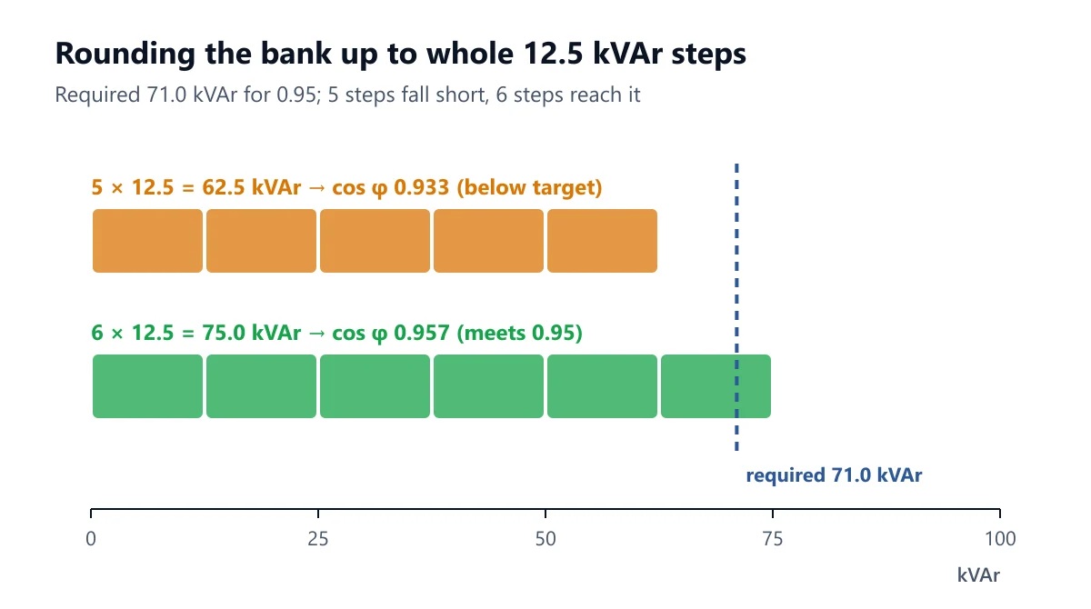
71.0 / 12.5 = 5.7, so the bank needs 6 steps: 6 × 12.5 = 75 kVAr. Five steps (62.5 kVAr) would leave the site at 0.933, below the target.
Step 4: what the installed bank achieves
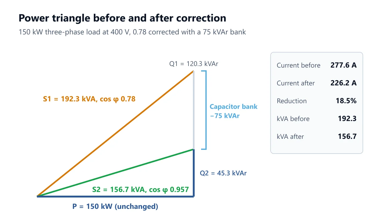
Reactive power before: 150 × 0.8023 = 120.3 kVAr; after: 120.3 − 75 = 45.3 kVAr
Apparent power: √(150² + 120.3²) = 192.3 kVA before, √(150² + 45.3²) = 156.7 kVA after
Corrected power factor: 150 / 156.7 = 0.957
Current: 192,308 / (√3 × 400) = 277.6 A before, 156,703 / 692.8 = 226.2 A after, an 18.5% reduction
Step 5: the capacitance
For a delta-connected three-phase bank, each of the three capacitors takes a third of the kVAr across the line voltage: C = Q / (2π f V²) = 25,000 / (2π × 50 × 400²) = 497 µF per phase. You will rarely specify capacitors in µF, since banks are sold by kVAr at a rated voltage, but it is a useful check against a nameplate when testing an old bank.
Choosing the target power factor
0.95 lagging is the usual target, and the reason is the shape of the curve. The kVAr needed per kW climbs steeply as the target approaches 1.0:
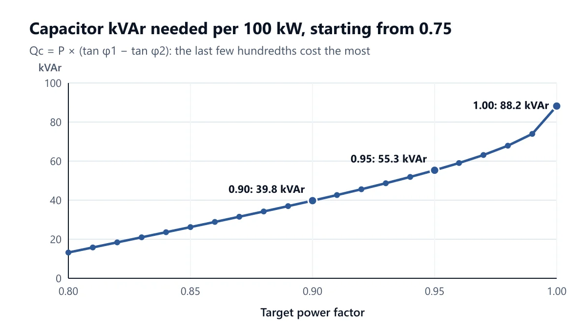
For our 150 kW site, correcting to exactly 0.95 takes 71.0 kVAr and brings the current down to 227.9 A. Going to 1.0 takes 120.3 kVAr, 69% more capacitors, to save another 11.4 A (216.5 A). Near unity the bank also risks pushing the site leading whenever the load drops.
Check the network tariff before fixing the target. Some distributors set a minimum power factor in their connection rules, and kVA-based demand tariffs reward every improvement, which changes the economics. We cover that side in a later article on kVA demand charges.
Fixed, automatic or at the motor
Central automatic bank at the main switchboard: a controller measures the power factor and switches steps in and out as the load changes. This is the normal choice for a site with varying load, and the reason the step size matters.
Fixed bank: one capacitor permanently connected. Fine where the reactive load barely changes, such as a transformer's no-load magnetising kVAr.
Individual correction at a motor: a capacitor switched with the motor. It also unloads the motor's own cable, but the capacitor must stay below the motor's no-load magnetising kVAr, or the motor can self-excite when it is switched off and still spinning. Use the maker's table.
Harmonics and detuned banks
Capacitors and the supply transformer form a resonant circuit. With variable speed drives, UPSs, LED drivers and other non-linear loads on site, that resonance can land near the 5th or 7th harmonic and amplify it, overheating the capacitors and blowing their fuses. Where non-linear load is significant, use a detuned bank with series reactors (on a 50 Hz system, commonly 7% detuning, tuned to 189 Hz) and have the harmonic distortion measured before and after. Capacitor units themselves are rated to IEC 60831-1.
Common mistakes
Using kVA instead of kW for P. The formula takes real power. Feeding it kVA overstates the bank.
Sizing from average power factor. Size from the load and power factor at the peak that matters (demand peak or transformer loading), not a monthly average.
Rounding down to the nearest step. As the example shows, 5 steps leave the site at 0.933. Round up, then check the corrected value.
Fixed correction on a variable load. A fixed 75 kVAr bank on our site at a light load of 60 kW (48.1 kVAr of reactive load) over-corrects by 26.9 kVAr, leaving the site at about 0.91 leading. A leading power factor raises the voltage and can upset generators and protection.
Ignoring harmonics. Standard capacitors on a site full of drives fail early. Measure first.
Forgetting the cable and protection to the bank. Capacitor current is continuous and sensitive to voltage and harmonics, so the supply cable and its protection are normally rated with a margin above the bank's nominal current. Follow the bank maker's recommendation, and size the cable as for any other feeder (see sizing cables for commercial and industrial use).
FAQ
How many kVAr do I need per kW?
It depends on where you start and where you finish. From 0.75 to 0.95 it is 0.553 kVAr per kW; from 0.80 to 0.95 it is 0.421 kVAr per kW; from 0.85 to 0.95 it is 0.291 kVAr per kW. Each is tan φ1 − tan φ2.
Does power factor correction reduce my kWh bill?
Not directly. The kWh is real energy and is unchanged. It cuts the current, so cable and transformer losses fall slightly, and on a kVA demand tariff it reduces the demand charge, which is usually the bigger saving.
Can I correct a single-phase load?
Yes, the formula is the same. The current is S × 1000 / V instead of dividing by √3 × V, and the whole capacitance sits across the one supply voltage. The calculator has a single-phase option.
Will correction free up transformer capacity?
Yes. A transformer is limited by current, so kVA. In the example, the same 150 kW drops from 192.3 kVA to 156.7 kVA, about 36 kVA of headroom for new load without upgrading the supply.
Size your capacitor bank
In the Power Factor Correction Calculator, pick three-phase or single-phase, enter the active power in kW, the voltage, the existing power factor and the target (it defaults to 0.95 and 25 kVAr steps; change the step to your bank's, or clear it for the exact value). It returns the kVAr required, the bank installed in whole steps, the corrected power factor, the capacitance, and the current and kVA before and after. If you are starting from motors, get their input kVAr from the Motor Full Load Current Calculator (the matching motor full load current guide explains it), and convert any kVA reading with the kVA Calculator. The other tools are listed in our free electrical calculators guide.
Work it out for your circuit
Free calculators, no sign-up needed.
Related articles
Continue reading more articles on this topic.
Industry KnowledgeAhmed Tayeh
kVA vs kW: Apparent, Real and Reactive Power Explained for Electricians
kW is the power that does the work, kVA is what the cables and transformers have…
Read more: kVA vs kW: Apparent, Real and Reactive Power Explained for Electricians
Industry KnowledgeAhmed Tayeh
kW to Amps: How to Convert Kilowatts to Amps for Single-Phase, Three-Phase and DC
The kW to amps formulas for single-phase, three-phase and DC supplies, why the p…
Read more: kW to Amps: How to Convert Kilowatts to Amps for Single-Phase, Three-Phase and DC
Industry KnowledgeSuheib
Motor Full Load Current: Converting Motor kW to Amps for Three-Phase Motors
A motor's kW rating is shaft output, not electrical input. Here is how to turn i…
Read more: Motor Full Load Current: Converting Motor kW to Amps for Three-Phase Motors