

Standards & ComplianceBy Suheib
MCB Trip Curves Explained: Type B, C and D, Inrush and Maximum Zs
Type B, C and D MCBs share the same overload behaviour but trip instantaneously at very different currents. Here is how to pick a curve for loads with inrush, and why the curve you pick sets the maximum earth fault-loop impedance and circuit length.

MCB trip curves describe how fast a miniature circuit breaker trips at each level of current. Type B, C and D breakers have the same thermal (overload) behaviour; they differ in the current that trips them instantaneously: about 3 to 5 times the rating for type B, 5 to 10 times for type C and 10 to 20 times for type D. The higher that magnetic trip current, the more inrush the breaker rides through, and the lower the earth fault-loop impedance the circuit must have for the breaker to disconnect a fault in time.
This article covers what the curves mean, how to choose a curve for loads with inrush, and how the curve sets the maximum Zs (Uo / Ia) and therefore the maximum circuit length. The worked example runs one 2.5 mm² circuit on B20, C20 and D20 breakers with the numbers the Fault Loop Impedance Calculator gives.
How to read MCB trip curves
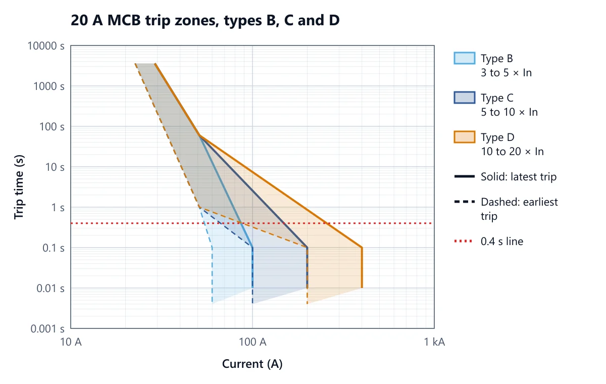
A trip curve is drawn on log–log axes: current along the bottom (usually as a multiple of the rating In), time up the side. Because every breaker has manufacturing tolerance, the standard does not define a line but a zone. The left edge of the zone is the earliest the breaker may trip; the right edge is the latest it is allowed to trip. A real breaker sits somewhere inside.
Every curve has two parts:
Thermal region (overload). A bimetal heats with the current, so the trip time falls as the current rises. AS/NZS 60898.1 sets the gates: the breaker must not trip within the conventional time (1 hour up to 63 A) at 1.13 In, must trip within that time at 1.45 In, and at 2.55 In must trip in more than 1 s but less than 60 s (for ratings up to 32 A). These gates are the same for B, C and D, which is why the three zones overlap at the top of the chart.
Magnetic region (short circuit and earth fault). A coil pulls the latch open with no intentional delay once the current passes the magnetic threshold. The breaker must not trip within 0.1 s at the lower end of the band and must trip within 0.1 s at the upper end.
The instantaneous trip multiples for type B, C and D
Type B: 3 to 5 × In. A B20 holds at 60 A and trips instantaneously by 100 A.
Type C: 5 to 10 × In. A C20 holds at 100 A and trips by 200 A.
Type D: 10 to 20 × In. A D20 holds at 200 A and trips by 400 A.
Between 2.55 In and the magnetic band the device standard sets no gate, so any curve drawn there is a model. The chart above joins the gates with straight log–log lines, which is how the CableHero Protection Coordination Calculator draws generic MCB zones. Manufacturers publish the real curves, and they are what you should read for discrimination studies.
Choosing a curve for loads with inrush
The curve is a trade-off. A low magnetic threshold clears faults quickly even on long circuits with small earth conductors; a high one tolerates switch-on surges. Pick the lowest curve the load will tolerate.
Type B suits resistive and lightly inductive loads with little inrush: heating, small lighting circuits, general power in homes, long runs where the fault current is low. It gives the longest permitted circuit length.
Type C is the usual choice for commercial and industrial final subcircuits: general power, fluorescent and LED lighting on larger circuits, small motors, IT equipment. That is why C curve MCBs are so common on commercial switchboards.
Type D is for high inrush: direct-on-line motors that are a large share of the breaker rating, transformers, welding sets, X-ray and large capacitive loads. Use it only when a C curve has actually been shown to nuisance trip, because it shortens the allowed circuit length sharply.
Inrush that causes nuisance tripping is a magnetic problem, not a thermal one. A direct-on-line motor draws several times its full load current for a few seconds while it accelerates (see motor full load current for the running current itself), and a bank of LED drivers can draw a very short but very high capacitor charging peak. If that peak passes the breaker's lower magnetic limit, the breaker trips in milliseconds regardless of its rating. Going up one rating rarely helps as much as going from B to C; changing the curve rarely helps as much as staggering the switch-on of large LED groups or using a soft starter.
How the curve sets the maximum Zs
AS/NZS 3000:2018 requires automatic disconnection of supply under earth fault: on final subcircuits up to 63 A supplying socket-outlets or hand-held equipment the device must disconnect within 0.4 s, and within 5 s on other circuits. For an MCB that is achieved by making sure the earth fault current is high enough to land in the magnetic region, which clears in well under 0.4 s. The condition is written as a maximum earth fault-loop impedance:
Zs ≤ Uo / Ia
where Uo is the nominal voltage to earth (230 V) and Ia the current that operates the breaker instantaneously. Ia is the trip curve multiple times the rating, so the curve is the single biggest factor in the maximum Zs. For a 20 A breaker:
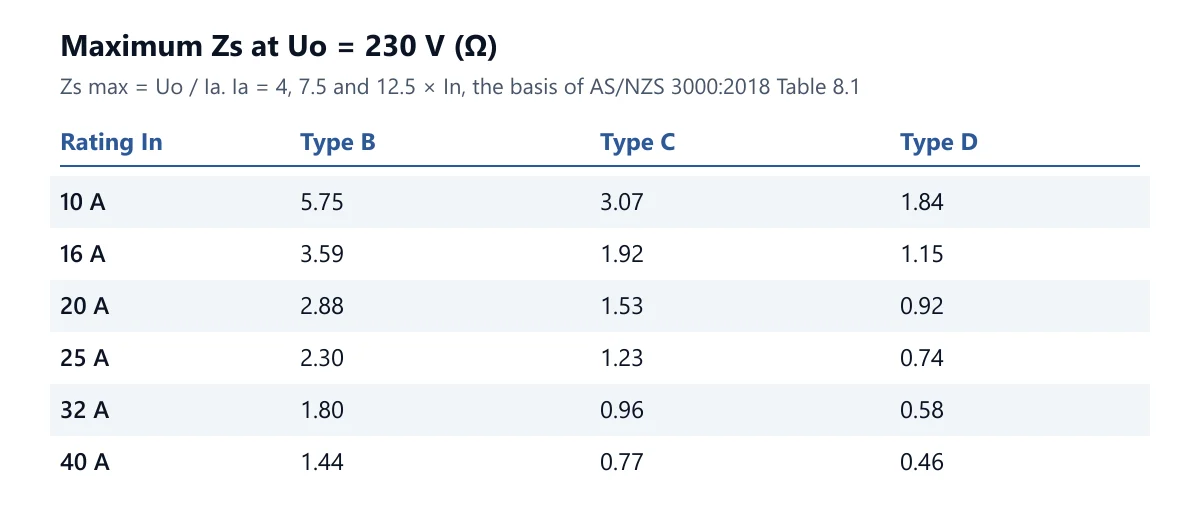
B20: Ia = 4 × 20 = 80 A, so Zs max = 230 / 80 = 2.875 Ω
C20: Ia = 7.5 × 20 = 150 A, so Zs max = 230 / 150 = 1.533 Ω
D20: Ia = 12.5 × 20 = 250 A, so Zs max = 230 / 250 = 0.920 Ω
The multiples 4, 7.5 and 12.5 × In for B, C and D are the basis of the maximum Zs values in AS/NZS 3000:2018 Table 8.1, and the ones the Fault Loop Impedance Calculator uses. The 2007 edition of the Wiring Rules used 5, 10 and 20 × In, so older tables, textbooks and test instruments may still show lower limits; work to the current edition.
Where the Zs of the circuit comes from
Zs is the whole loop: the supply transformer, the distributor's active and neutral, the consumer mains, then the circuit's active out to the fault and its protective earth back to the main earthing terminal and the MEN link. Before anything is built you only know your own cable, so AS/NZS 3000:2018 Appendix B5.2.2 assumes 80% of Uo is available at the origin of the circuit during a fault. The calculator therefore works:
Zs = L × (Z_active + Z_earth) / 1000 / 0.8
with Z in Ω/km from the AS/NZS 3008.1.1:2025 resistance and reactance tables at the insulation's maximum operating temperature (75 °C for V-75), and L in metres. For the theory of the loop itself, see our guide to fault loop impedance.
Worked example: one circuit on B20, C20 and D20
A 230 V single-phase final subcircuit in 2.5 mm² two-core and earth V-75 TPS, copper, 45 m long, with the 2.5 mm² earth AS/NZS 3000:2018 Table 5.1 gives for a 2.5 mm² active. Fault level at the board 6 kA.
Cable data. Active and earth Rc at 75 °C = 9.01 Ω/km, Xc = 0.102 Ω/km, so each conductor is √(9.01² + 0.102²) = 9.011 Ω/km.
Cable impedance. 45 m × (9.011 + 9.011) / 1000 = 0.811 Ω.
Circuit Zs. 0.811 / 0.8 = 1.014 Ω. This is the same for all three breakers: the cable does not care which curve protects it.
Compare with each curve. B20: 1.014 ≤ 2.875 Ω, pass. C20: 1.014 ≤ 1.533 Ω, pass. D20: 1.014 > 0.920 Ω, fail.
Maximum length. Zs is proportional to length, so L max = 45 × Zs max / 1.014: B20 127 m, C20 68 m, D20 40 m.
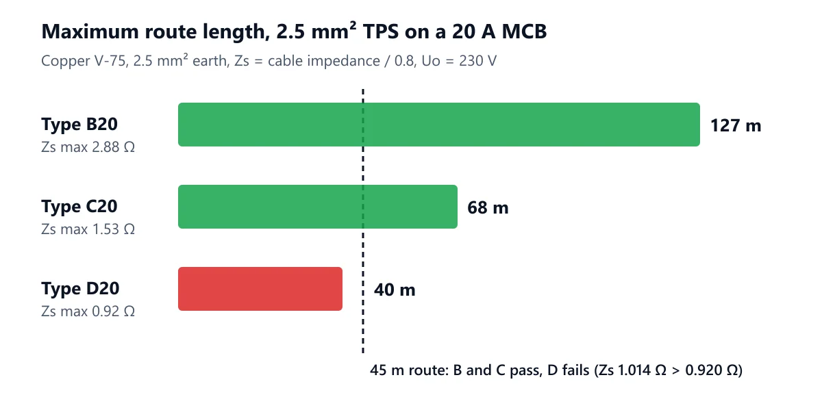
The calculator also reports the prospective earth fault current at the far end: 0.24 kA. Table 8.1 takes 250 A as the operating current of a D20, so at 45 m the breaker is not shown to trip instantaneously and a fault could sit in the thermal region for seconds. The fix is not a bigger breaker: either keep the C curve, shorten the run to under 40 m, or increase the conductor sizes (a 4 mm² TPS has a 2.5 mm² earth per Table 5.1, so the gain is smaller than the size change suggests; a separate larger earth helps more).
Common mistakes with MCB trip curves
Swapping a C for a D to stop nuisance tripping without rechecking Zs. The maximum Zs drops by 40% (1.533 to 0.920 Ω for a 20 A), so a circuit that complied can stop complying. Re-run the loop impedance every time the curve changes.
Treating the curve as a rating. A C32 and a D32 carry the same load and protect the cable against overload the same way. The curve does not change Ib ≤ In ≤ Iz; it changes short-circuit and earth fault behaviour.
Using the line voltage for Uo on a three-phase circuit. Uo is the voltage to earth: 400 / √3 = 230.9 V on a 400 V system, not 400 V. Using 400 V allows a loop √3 times too high.
Forgetting the cable heats up. Loop impedance must be worked at the conductor's operating temperature. A measurement on a cold circuit reads lower than the same circuit under full load.
Relying on the calculation alone. AS/NZS 3000:2018 requires the fault loop to be verified when the installation is tested; the design figure tells you whether it should pass, the test confirms it does.
Assuming an RCD fixes everything. An RCD gives fast earth fault disconnection, but the MCB still has to clear short circuits between active and neutral within the cable's withstand. Read our fault loop impedance tips for the cable sizing side.
FAQ
What is the difference between B, C and D curve MCBs?
Only the instantaneous (magnetic) trip current: 3 to 5 × In for type B, 5 to 10 × In for type C and 10 to 20 × In for type D. Their overload behaviour, governed by the 1.13 In and 1.45 In gates, is the same.
Which MCB curve should I use for a motor?
Start with type C. Most small motors start comfortably on a C curve breaker sized for the circuit. Move to type D only for high inertia or direct-on-line motors that are a large share of the breaker rating, and recheck the maximum Zs when you do.
What is the maximum Zs for a C20 MCB?
1.53 Ω at 230 V: Uo / Ia with Ia = 7.5 × 20 = 150 A, the basis of AS/NZS 3000:2018 Table 8.1 and of the CableHero calculator.
Can I replace a type C MCB with a type B?
Usually yes, and it improves the fault loop margin, provided the load does not have enough inrush to trip a B curve. Lighting with many LED drivers and motor circuits are the usual exceptions.
Check your circuit's trip curve and length
Open the Fault Loop Impedance Calculator, pick the MCB curve and rating, enter the cable size, insulation, route length and the fault level at the board, and it gives Zs, the Uo / Ia limit and the maximum length straight away. Change the curve from C to D and watch the maximum length fall before you make the swap on site. To check the whole cable at once (current rating, voltage drop, short-circuit withstand and fault loop together), use the Cable Size Calculator. For the wider rules, our AS/NZS 3000 guide summarises the Wiring Rules, and the standard itself is available from Standards Australia.
Work it out for your circuit
Free calculators, no sign-up needed.
Related articles
Continue reading more articles on this topic.

Product GuidesAhmed Tayeh
Effective Ways to Create AS/NZS-Compliant Single Line Diagrams
Single-line diagrams (SLDs) are simplified schematics that represent an electric…
Read more: Effective Ways to Create AS/NZS-Compliant Single Line Diagrams
Standards & ComplianceAhmed Tayeh
How to Integrate Fault Loop Impedance in Your Cable Sizing Calculations
Beyond matching conductor size to design current, correct cable sizing should al…
Read more: How to Integrate Fault Loop Impedance in Your Cable Sizing Calculations
Product GuidesAhmed Tayeh
How CableHero Ensures Calculations and Results are AS/NZS 3008 and 3000 Compliant
The AS/NZS 3008 and AS/NZS 3000 help ensure the safety, reliability, and complia…
Read more: How CableHero Ensures Calculations and Results are AS/NZS 3008 and 3000 Compliant