Ignoring Cable Derating Factors: A Costly Design Mistake
18Sep
Ahmed Tayeh
Cable Sizing
Ignoring Cable Derating Factors: A Costly Design Mistake
Many designers look at a cable manufacturer's current-carrying capacity tables and assume that the published rating can be used directly for their project. In reality, those ratings are based on specific installation conditions that rarely reflect actual site environments. This is where cable derating factors become critical.
Cable derating factors are what bridge the gap between the published rating and the cable's actual current-carrying capacity in the field. Miss them and the result is an undersized cable that overheats in service, degrades prematurely, and may fail in ways that are expensive to diagnose and even more expensive to fix.
This guide covers every cable derating factor required under AS/NZS 3008.1.1:2025, the formula for combining them, worked examples with real numbers, and the sectors where getting this wrong has the highest consequences.
What Is a Cable Derating Factor?
Derating factors are correction factors applied to a cable's current-carrying capacity to account for real-world installation conditions.
Every conductor generates heat when current flows through it. That heat must dissipate into the surrounding environment fast enough to keep the conductor temperature below the insulation's rated maximum. When the surrounding environment is hotter, more congested, deeper underground, or thermally insulating, heat dissipation is restricted. To prevent the conductor from exceeding its temperature limit, the maximum allowable current must be reduced.
The cable derating factor is expressed as a decimal between 0 and 1. A factor of 0.85 means the cable can carry only 85% of its published rated current under the applicable installation conditions. A factor of 0.55 means it can carry only 55%.
Derating factors are a mandatory part of cable sizing under AS/NZS 3008.1.1. Any cable sizing calculation that ignores applicable derating factors is non-compliant, regardless of whether the cable's base rating exceeds the design current.
Why Do Derating Factors Matter?
A cable that appears adequately sized under standard conditions can become overloaded once it is installed in the field. The consequences of ignoring derating may include:
Cable overheating
Premature insulation degradation
Increased maintenance requirements
Reduced system efficiency
Expensive cable replacement projects
In large-scale renewable energy and infrastructure projects where kilometers of cable may be installed underground, seemingly small design errors can quickly translate into significant financial impacts.
What Is the Cable Derating Formula Under AS/NZS 3008.1.1?
The derated current-carrying capacity of a cable is calculated as:
Iz = It × Ka × Kg × Kd × Ks (× Ki where applicable)
Iz = Derated current-carrying capacity (A)
It = Base current-carrying capacity from AS/NZS 3008.1.1 tables for the cable type and installation method (A)
Ka = Ambient temperature correction factor
Kg = Grouping factor (for cables installed in proximity to other loaded cables)
All applicable factors are multiplied together. The combined derating factor is the product of every factor that applies to the installation. The result can be significantly lower than any individual factor suggests.
The Three-Check Cable Sizing Rule
Iz is only one check. Under AS/NZS 3000:2018 Clause 3.3, the fundamental cable sizing inequality is: Ib ≤ In ≤ Iz.
Ib = The design current
In = The rated current of the protective device
The derated Iz must be at least equal to In, which must be at least equal to Ib. A cable that passes the derating check still needs to pass voltage drop (Clause 3.6, 5% maximum) and fault loop impedance (Zs ≤ Zmax) before it is correctly sized. The cable derating factor governs the current-carrying check, not the whole sizing calculation.
What Is the Importance of AS/NZS 3008.1.1?
AS/NZS 3008.1.1 provides the framework for selecting cables and determining current-carrying capacities under various installation conditions.
The standard recognizes that cable performance is heavily influenced by the environment in which it operates. Rather than relying solely on base cable ratings, engineers must evaluate the actual installation conditions and apply relevant correction factors where required.
Importantly, multiple derating factors often apply simultaneously. A cable may be affected by its installation method, burial depth, cable grouping arrangement, ambient temperature, and soil characteristics all at the same time. The combined impact of these factors is where significant design errors often occur.
What Are the Key Derating Factors Engineers Must Consider?
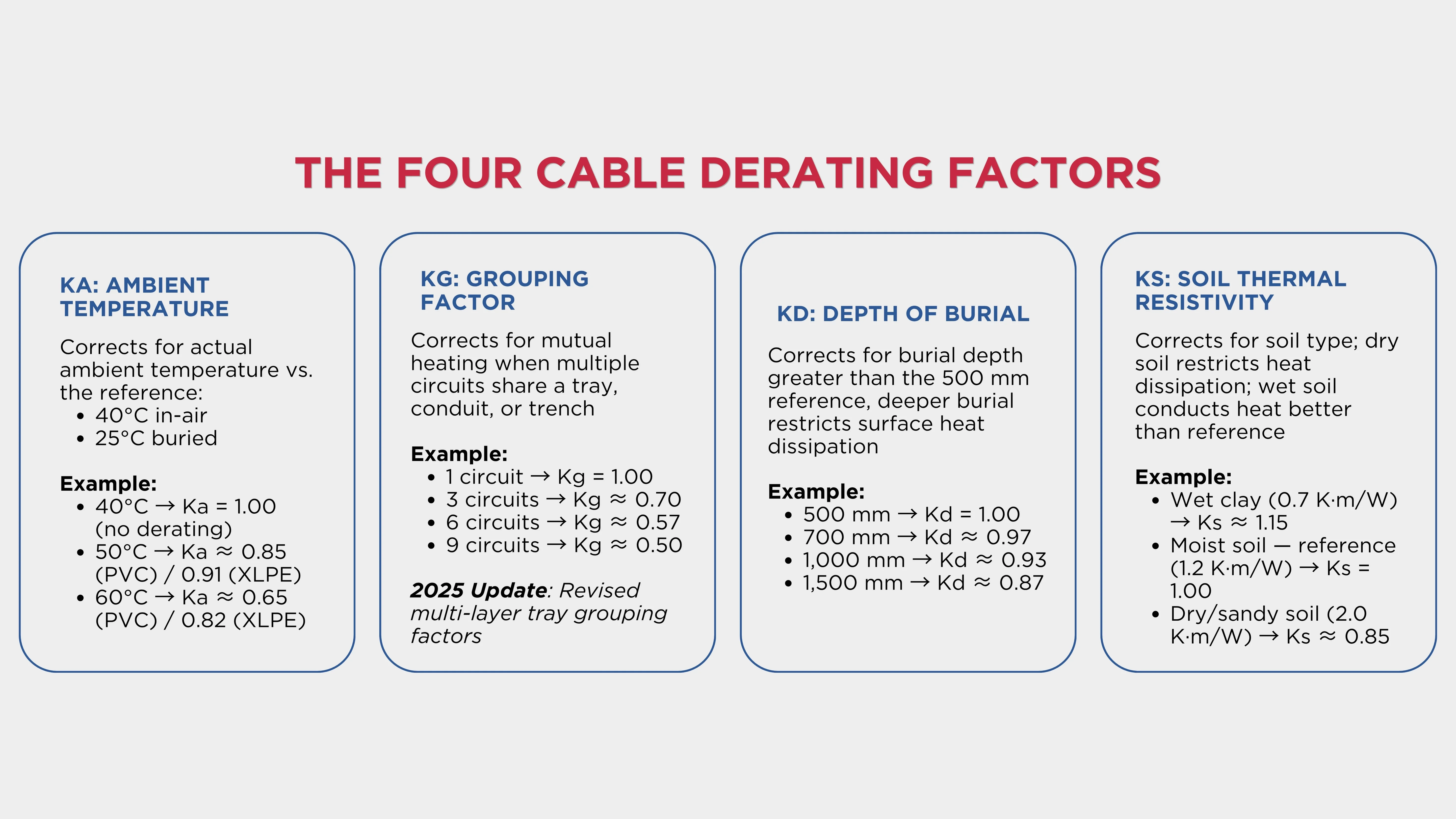
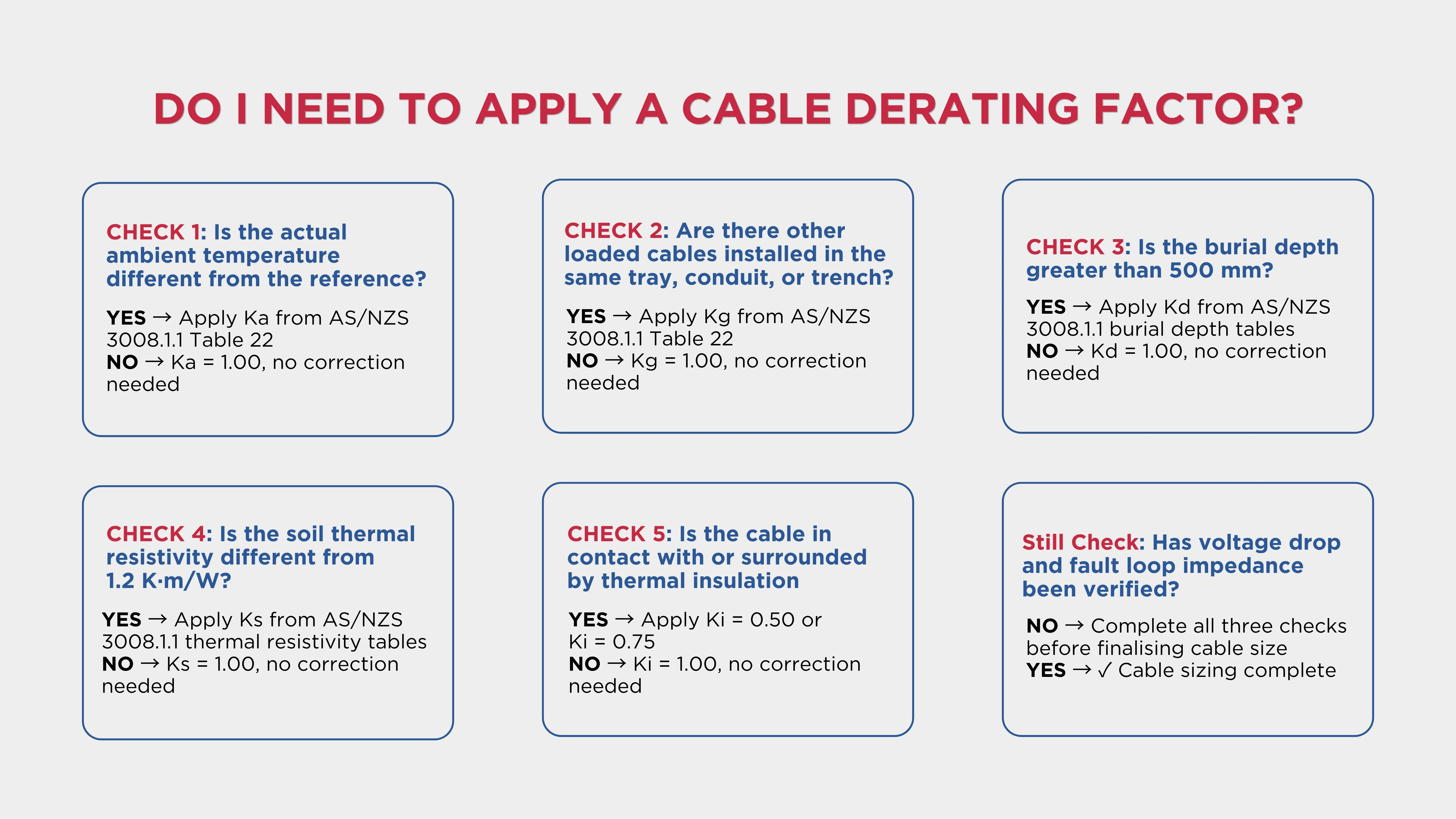
C16.2.webp384.36 KB One of the most common misconceptions in cable sizing is assuming that a single derating factor determines cable performance. In reality, several installation variables can collectively influence a cable's current-carrying capacity.
Ka: Ambient Temperature Correction Factor
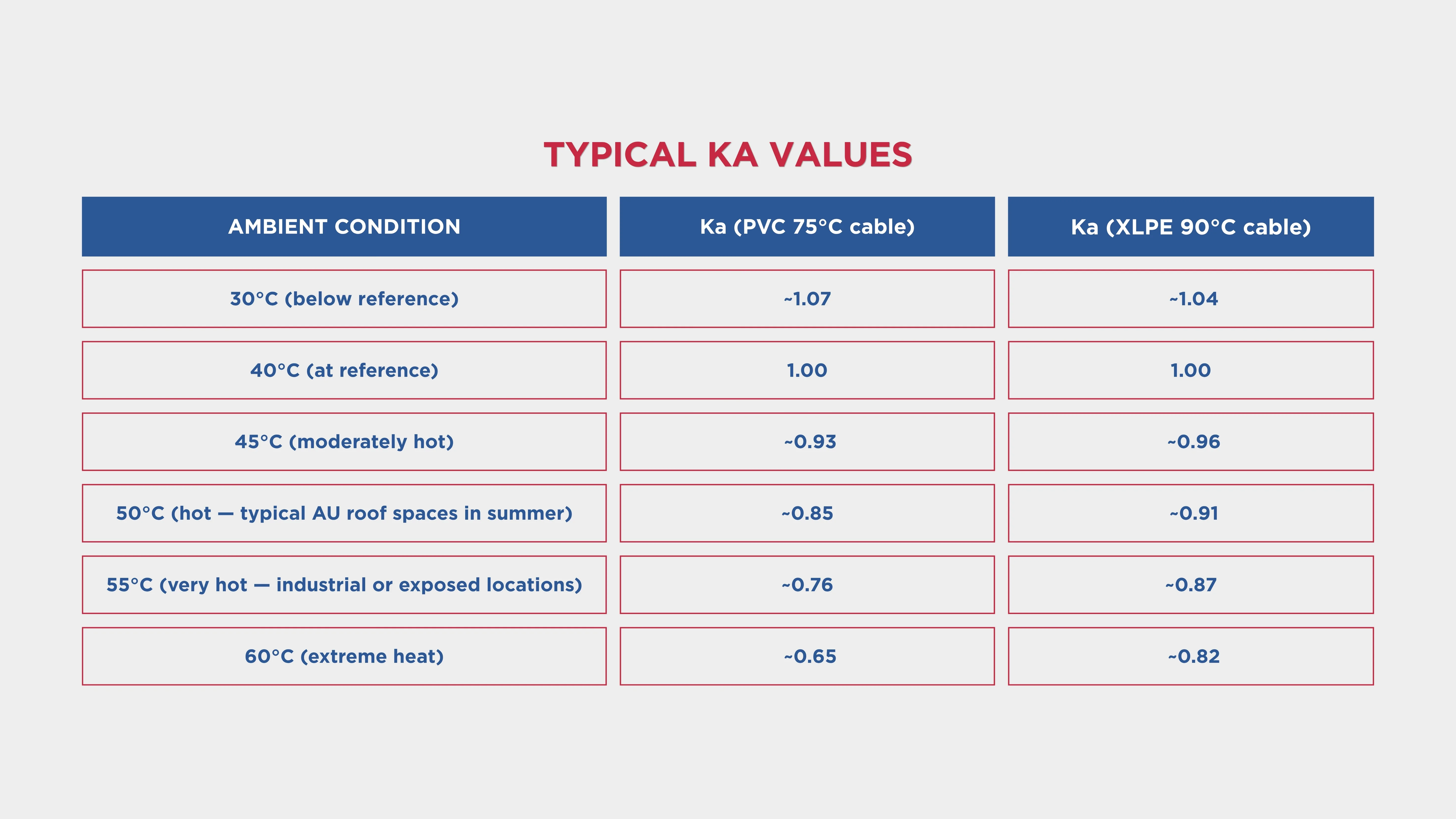
The ambient temperature correction factor (Ka) accounts for the difference between the actual ambient temperature at the installation location and the reference temperature used in the AS/NZS 3008.1.1 tables.
Reference Temperatures Under AS/NZS 3008.1.1:2025
In-Air Installation = 40°C
Buried Direct or In Duct = 25°C
If the actual ambient is higher than the reference temperature, Ka is less than 1; the cable must be derated. If the actual ambient is lower, Ka can be greater than 1, providing a small enhancement (though this is rarely relied upon in conservative design practice). C16.3.webp172.85 KB Where This Matters Most in Australia
In-roof-space cable installations in northern Australia are particularly vulnerable to Ka derating. Roof spaces in Queensland, the Northern Territory, and Western Australia can reach 50–65°C during summer.
A cable sized at the standard 40°C reference temperature without Ka adjustment can be carrying significantly more than its derated capacity in these conditions, reducing insulation life and potentially causing premature failure.
For XLPE-insulated cables, the higher operating temperature rating (90°C vs. 75°C for PVC) means Ka is less aggressive at elevated temperatures. Where high ambient temperatures are a design constraint, specifying XLPE instead of PVC reduces the Ka derating required.
Kg: Grouping Factor
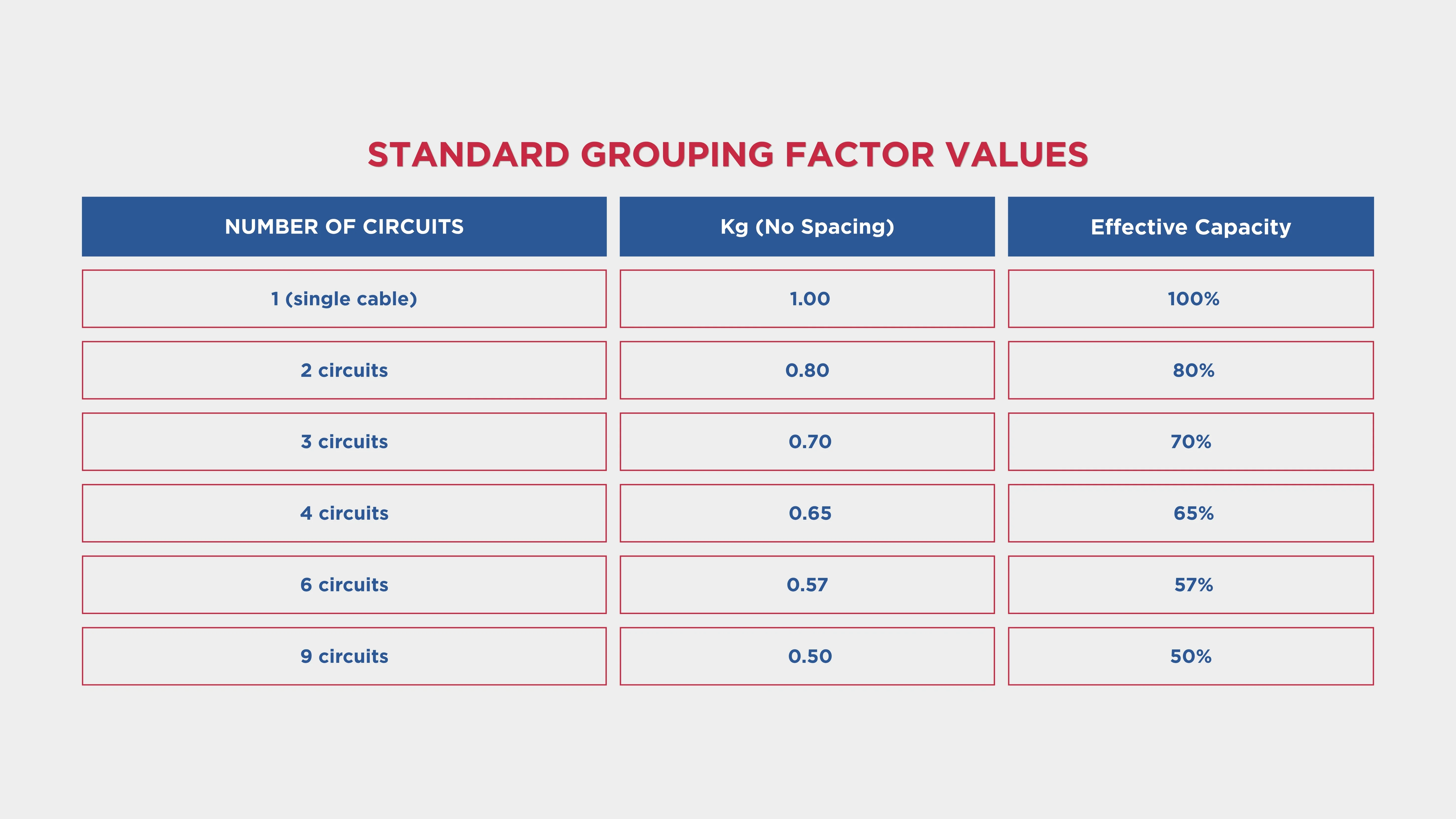
The grouping factor (Kg) accounts for the mutual heating effect between cables installed in proximity. When cables are bunched together, heat from each cable raises the ambient temperature experienced by its neighbours. Every cable in the group must be derated to account for the elevated surrounding temperature.
When multiple cables are installed close together, they generate heat collectively. This raises the overall temperature, reducing their ability to cool. Each cable must be derated using a grouping correction factor to prevent overheating. C16.4.webp144.32 KB Where cables are spaced apart by at least one cable diameter, grouping factors are more favourable. AS/NZS 3008.1.1 Table 22 provides values for different spacings and installation configurations. Always apply the correct table column for the actual installation method.
Multi-Layer Cable Trays: The AS/NZS 3008.1.1:2025 Update
Field studies and finite-element thermal modelling conducted since 2017 revealed that the grouping factors in Table 25 were non-conservative for certain enclosed-tray configurations, particularly when cables are tightly packed in three or more layers.
The 2025 edition of AS/NZS 3008.1.1 revised the grouping factors for multi-row cable tray configurations. Designs based on the 2017 edition grouping factors for multi-layer trays may not comply with the 2025 edition requirements.
Engineers reviewing or modifying existing installations should verify that grouping factors have been updated to the 2025 values where multi-layer trays are used.
Where Group Derating Has the Highest Impact
Large cable bunches in data centres, industrial motor control centres, and the DC combiner cable runs on utility-scale solar farms frequently involve six or more circuits in close proximity.
In these cases, Kg can reduce the cable's effective capacity by 40–50%, forcing significant cable upsizing above what an isolated cable rating would suggest.
Kd: Depth of Burial Factor
For underground cable installations, the depth at which the cable is buried affects its ability to dissipate heat to the surface. Cables buried deeper than the standard reference depth lose some convective and conductive cooling path to the surface, raising their steady-state operating temperature.
The reference burial depth in AS/NZS 3008.1.1 for LV cables is 500 mm. For cables buried at the standard depth, Kd = 1.0.
When Depth Changes in Practice
Many projects install cables at greater depths than the initial design assumes. Road crossings, existing underground services conflicts, civil design changes, and environmental constraints can all push cables deeper. Each change that increases burial depth reduces Kd and must trigger a cable sizing review.
For utility-scale solar and wind farm projects, cable routes often cross unsealed and sealed roads where burial depths of 900 mm–1,200 mm are required. At these depths, Kd is typically in the range of 0.90–0.93 for a standard soil environment.
Ks: Soil Thermal Resistivity Factor
Soil thermal resistivity describes how easily heat flows through the soil surrounding a buried cable. High thermal resistivity means heat flows slowly. The soil acts like an insulator, and cable temperature rises for a given current. Low thermal resistivity means heat dissipates effectively, and the cable can carry more current safely.
AS/NZS 3008 uses 1.2 K·m/W as the reference thermal resistivity. This means AS/NZS 3008 tabulated ratings are higher for buried cables, but require more aggressive derating if the actual soil is drier.
Why Soil Investigation Matters
For major cable routes, the difference between the reference soil condition (1.2 K·m/W) and the actual site condition can be significant. Inland Australian soils, particularly sandy or rocky substrates in arid areas, commonly have thermal resistivity values of 2.0–3.0 K·m/W.
Using the reference value (1.2 K·m/W) in these conditions produces an optimistic cable rating that does not reflect actual performance.
On large projects, thermal resistivity investigation is a worthwhile investment. The cost of investigation is small compared to the cost of replacing an undersized cable route that overheats in service.
Where selected thermal backfill is specified, thermal resistivity of approximately 1.0 K·m/W can typically be guaranteed, eliminating the uncertainty of native soil conditions and allowing the cable route to be sized to a known, conservative value.
Ki: Thermal Insulation Factor
The thermal insulation factor (Ki) applies when cables are in contact with or completely surrounded by thermally insulating material. This is most commonly encountered in residential roof spaces where bulk insulation is laid directly over fixed wiring.
Cables installed in or surrounded by thermal insulation are restricted from dissipating heat. This reduces the current-carrying capacity, requiring a thermal insulation correction factor.
A cable completely surrounded by thermal insulation has almost no ability to dissipate heat to the surrounding environment. Under this condition:
Ki = 0.50
This is the most severe single derating factor in the standard. The cable can carry only 50% of its base current rating when completely surrounded by insulation. Where a cable is in contact with thermal insulation on one side (but not surrounded), a less severe correction factor applies, depending on the length of cable in contact and the type of insulation.
Critical Practical Implications
This is one of the most consistently misapplied derating conditions in Australian residential electrical work. Cables clipped to the top of ceiling joists before thermal insulation is installed can subsequently be buried under insulation batts.
A 2.5 mm² cable rated at 24 A for a circuit protected by a 20 A breaker passes the current-carrying check in isolation, but when buried in insulation, its derated capacity drops to 12 A. The 20 A protective device no longer provides adequate cable protection.
AS/NZS 3000 Clause 3.3.2.13 explicitly addresses cables passing through bulk thermal insulation. Current-carrying capacity must be calculated according to the length of cable in the insulation using the Ki factor. C16.5.webp371.74 KB
The Combined Derating Effect: A Worked Example
The full significance of cable derating factors only becomes apparent when multiple factors are combined on a single installation. This is where the most serious design errors occur.
Scenario: Underground MV Feeder — Utility-Scale Solar Farm (Inland Australia)
From AS/NZS 3008.1.1 tables for 240 mm² copper, XLPE insulation, direct buried: It = 450 A (at reference conditions: 25°C, 1.2 K·m/W, 500 mm depth, single circuit)
Step 2: Apply Derating Factors
Ka — Soil temperature 30°C (reference is 25°C for buried): 0.96
Kg — 4 circuits flat with 100 mm spacing: 0.74
Kd — Burial depth 900 mm (reference is 500 mm): 0.93
The 240 mm² cable derated to 253 A is less than the 380 A design current.
The cable is undersized.
Step 5: Required Cable Size
Working backwards: It ≥ 380 / 0.562 = 676 A
A 630 mm² cable (It ≈ 650 A) is still marginally insufficient. A 800 mm² cable (or two 400 mm² per phase in parallel) is required to carry 380 A under these installation conditions.
The combined derating factor of 0.562 is what forces this significant cable upsizing decision. Had the designer used the base 450 A rating and specified 240 mm² without applying derating factors, the cable would be overloaded at 380 A in service.
What Is the Real Cost of Ignoring Cable Derating Factors?
The original design calculus reverses quickly when derating factors are ignored. On a utility-scale solar farm with 40 kilometres of underground MV collection cable, the difference between a correctly derated cable size and an undersized cable manifests as:
Elevated Operating Temperature: Accelerating insulation degradation and reducing cable life from the designed 30–40 years toward 15–20 years
Increased Resistive Losses: A cable operating at the upper limit of its temperature rating has higher resistance than the design assumed, increasing energy losses across the collection network and reducing annual generation
Reduced Maximum Power Throughput: If the farm is uprated or generation exceeds the original design current, the undersized cable becomes a bottleneck before the switchgear or transformers
Replacement Before End of Asset Life: Replacing buried MV cables on an operating solar farm requires significant civil work, extended outage periods, and costs that dwarf the original cable procurement savings
The cheapest cable at procurement is not always the most economical cable over the life of the asset. Select appropriate soil backfill for critical buried cables to achieve a known, low thermal resistivity rather than relying on native soil conditions.
Apply Every Derating Factor Correctly with CableHero
Cable derating factors are the part of cable sizing where small errors have large consequences and where the complexity of combining four or five factors across multiple circuit types on a large project makes manual calculation both time-consuming and error-prone.
CableHero is professional cable sizing software built specifically for Australian electricians and engineers, fully aligned with AS/NZS 3000:2018 and AS/NZS 3008.1.1:2025. With CableHero, every cable derating factor is applied automatically based on the installation conditions.
With CableHero, you can:
Apply Ka, Kg, Kd, and Ks automatically from AS/NZS 3008.1.1:2025 tables
Run all three cable sizing checks simultaneously
Size DC cables for solar PV, BESS, and EV charging under the new DC cable provisions
Generate compliant PDF cable schedules and reports ready for certification and DNSP submission, with every derating factor and its source clearly documented
Whether you're designing a residential fit-out, a commercial building cable schedule, or the MV collection network for a utility-scale solar farm, CableHero takes the derating complexity off your hands. Use CableHero for your cable sizing for free today.
FAQ
What is a cable derating factor and why is it required under AS/NZS 3008.1.1?
A cable derating factor is a correction factor applied to a cable's published current-carrying capacity to account for installation conditions that reduce the cable's ability to dissipate heat. When actual installation conditions differ from these references, which they almost always do, one or more derating factors must be applied.
How do you calculate the combined cable derating factor?
The combined cable derating factor is calculated by multiplying all applicable individual factors: Combined factor = Ka × Kg × Kd × Ks (× Ki where applicable). The derated current-carrying capacity is then: Iz = It × combined factor, where It is the base cable rating from AS/NZS 3008.1.1 tables for the cable type and installation method.
What changed for cable derating factors in AS/NZS 3008.1.1:2025?
The December 2025 edition of AS/NZS 3008.1.1 introduced three significant changes that affect cable derating calculations: (1) revised grouping factors for multi-layer cable trays, (2) a new soil thermal resistivity row was added for very dry soil at 3.0 K·m/W with a derating factor of approximately 0.71, (3) explicit DC cable current-carrying capacity tables and derating methodology were added for solar PV string cables up to 1,500 V DC, BESS cables, and EV charging DC circuits.


 Cable Sizing