How Ambient Temperature Influences Cable Sizing in Australia
02Oct
Ahmed Tayeh
Cable Sizing
How Ambient Temperature Influences Cable Sizing in Australia
Every current-carrying capacity table in AS/NZS 3008.1.1 rests on a specific assumption: the ambient temperature around the cable is either 40°C (for in-air installations) or 25°C (for buried installations). When actual site conditions exceed these reference temperatures, those published ratings no longer apply without correction. If this effect is not properly considered, a cable that appears adequately sized may operate above its intended temperature limits, leading to reduced performance, accelerated insulation ageing, and potential system failures. For projects ranging from commercial buildings and industrial facilities to solar farms and battery energy storage systems (BESS), understanding how ambient temperature influences cable selection is essential for ensuring safe, compliant, and reliable electrical installations.
Why Does Ambient Temperature Matters for Cable Sizing?
A cable generates heat when it carries current. This is a fundamental physical consequence of conductor resistance. That heat must dissipate into the surrounding environment quickly enough to keep the conductor temperature below the insulation's rated maximum. When the surrounding environment is hotter, the temperature difference between the cable and its surroundings is smaller. A smaller temperature difference means slower heat transfer, and a cable that must be run at lower current to stay below its temperature limit. The reference ambient is 40°C for in-air installations and 25°C for buried installations. Hotter conditions reduce capacity. This is why a cable correctly sized for a 40°C environment will overheat if installed in a 55°C roof cavity without applying Ka. The current hasn't changed. The physics have. The cable simply cannot shed heat fast enough to stay within its rated temperature.
What Is the Consequence of Ignoring Ambient Temperature?
A cable operating above its rated conductor temperature experiences accelerated insulation ageing. The commonly cited Arrhenius rule for electrical insulation suggests that every 10°C increase in operating temperature approximately halves insulation service life. A cable designed for 30 years of service at its rated temperature may deliver only 15 years if it consistently operates 10°C above that limit. The practical consequence for projects: a cable that appears to pass current-carrying capacity at the time of installation but operates without Ka correction will:
Run hotter than designed throughout its service life
Degrade insulation faster than the asset life assumes
Increase risk of thermal fault before the planned replacement date
In extreme cases, fail in service with no visible warning signs
What Is the Ka Formula Under AS/NZS 3008.1.1:2025?
The Ka factor is the square root of the rated temperature minus the ambient, divided by the rated temperature minus the reference. Ka = √[(T_rated − T_ambient) / (T_rated − T_reference)]
T_rated = Maximum rated conductor temperature (75°C for PVC, 90°C for XLPE)
T_ambient = Actual ambient temperature at the installation location (°C)
T_reference = Reference ambient temperature from AS/NZS 3008.1.1 (40°C for in-air, 25°C for buried)
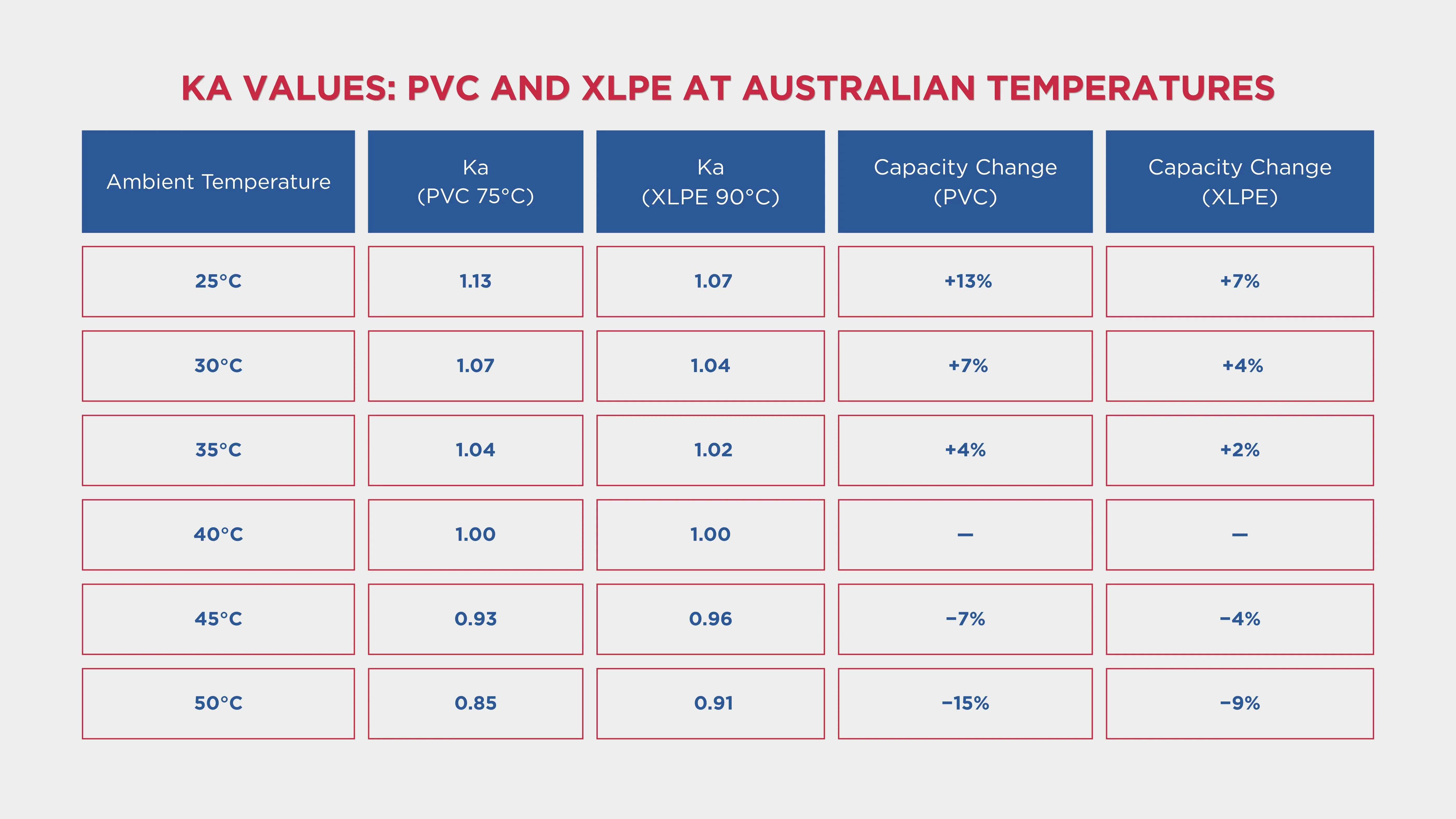
How Ka Works in Practice: When the actual ambient equals the reference temperature, Ka = 1.00, no correction is needed. When the actual ambient exceeds the reference, Ka becomes less than 1, the cable must be derated. The larger the excess above reference temperature, the smaller Ka becomes, and the more aggressive the capacity reduction. When the actual ambient is below the reference temperature, Ka becomes greater than 1. In practice, this enhancement is rarely relied upon in conservative design, but it is legitimate to apply where actual ambient conditions are documented to be consistently below the reference.
Ka Values: PVC and XLPE at Key Australian Temperatures
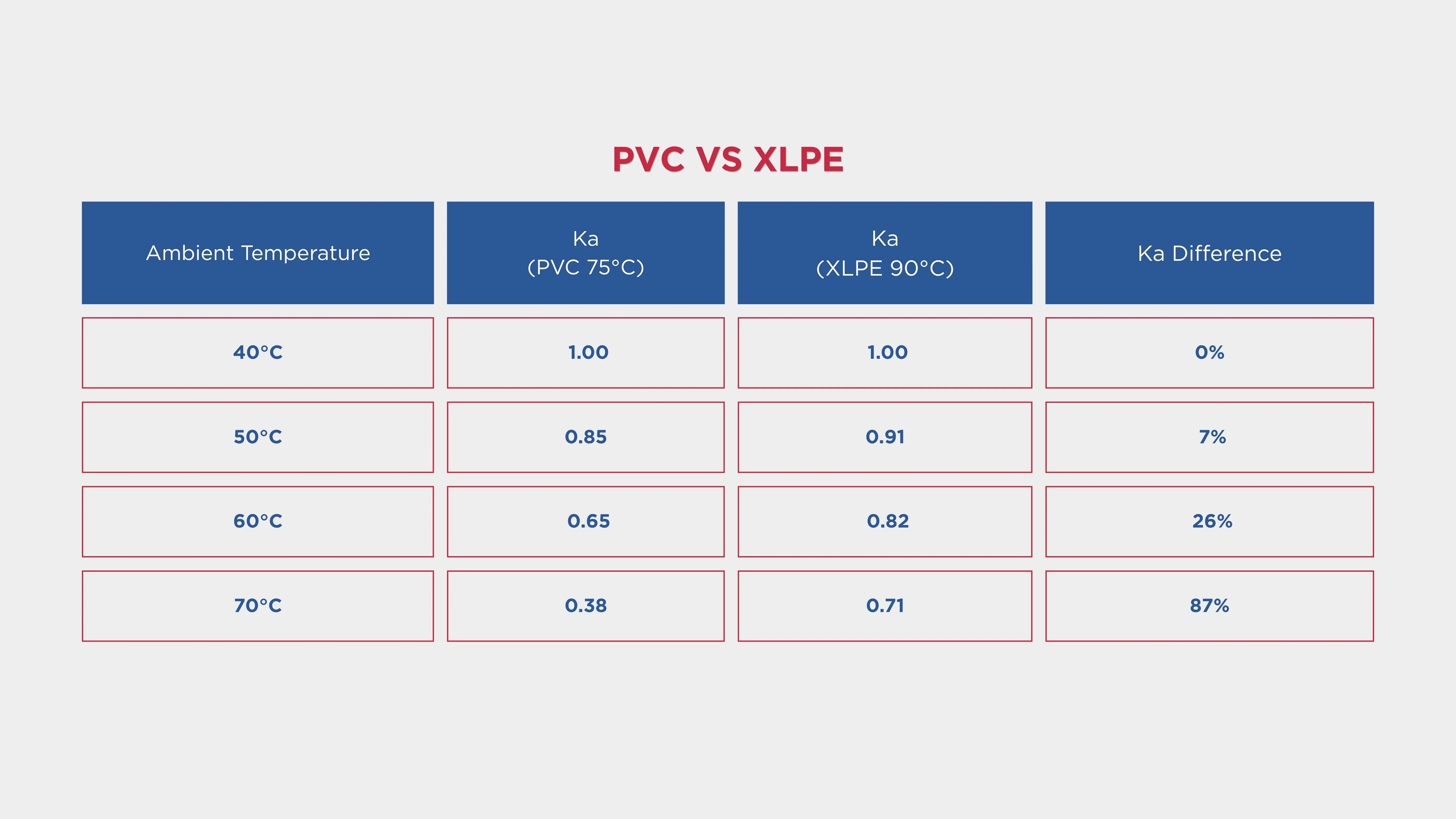
The table below gives Ka correction factors for PVC (75°C rated) and XLPE (90°C rated) cables at ambient temperatures commonly encountered in Australian installations. Values are calculated using the AS/NZS 3008.1.1 formula for in-air installations (reference: 40°C). C17.2.webp165.75 KB Roof cavities in Australian climates can reach ambient temperatures of up to 70°C during summer. This significantly exceeds the 40°C reference ambient temperature assumed in the standard's base current-carrying capacity tables. What This Table Shows: PVC cables are significantly more vulnerable to temperature than XLPE. At 55°C ambient, a PVC cable's allowable current is reduced by 24%, while the same-size XLPE cable is reduced by only 13%. At 70°C, a PVC cable retains only 38% of its base rating, while XLPE retains 71%. This comparison has a direct practical implication: in any installation where ambient temperatures are expected to significantly exceed 40°C, XLPE should be strongly preferred over PVC. The reduced Ka correction required for XLPE frequently allows a smaller cable cross-section to remain compliant, offsetting the higher material cost of XLPE over PVC.
How to Apply Ka? The Corrected Current-Carrying Capacity Formula
The Ka correction factor is applied as a multiplier to the base current-carrying capacity from the AS/NZS 3008.1.1 tables: Iz = It × Ka
Iz = Derated current-carrying capacity (A)
It = Base current-carrying capacity from AS/NZS 3008.1.1 for the cable type and installation method (A)
Ka = Ambient temperature correction factor for the actual site temperature
This gives the maximum current the cable can carry at the actual ambient temperature. The design current (Ib) must not exceed Iz.
When Other Correction Factors Also Apply
Ka rarely operates alone. When additional correction factors are applicable, they are multiplied together with Ka: Iz = It × Ka × Kg × Kd × Ks The table base rating assumes a single isolated cable at the reference ambient temperature. Real installations rarely match those assumptions. Three multiplicative correction factors correct for the deviation. The combined correction can be far more severe than Ka alone. A cable at 55°C ambient (Ka = 0.76 for PVC) grouped with four other circuits (Kg ≈ 0.65) has a combined correction factor of approximately 0.49, meaning the cable can carry less than half its base rating. This combined effect is why correct application of all applicable correction factors, multiplied together, is non-negotiable under AS/NZS 3008.1.1.
Where Does Ambient Temperature Have the Highest Impact in Australia?
Roof Spaces and Ceiling Cavities
This is the installation environment where ambient temperature correction is most consistently under-applied. Roof cavities in Australian climates can reach ambient temperatures of up to 70°C during summer. Poorly ventilated roof spaces in Queensland, Western Australia, the Northern Territory, and inland New South Wales and Victoria regularly measure 60–70°C during summer peak periods. These temperatures are normal operating conditions.
Solar PV Installations; String Cables on Panel Structures
For rooftop solar installations, the enclosed conduit scenario is used as the more conservative design condition, as the combination of solar irradiance on panels and enclosed conduit in a roof cavity creates ambient temperatures that can exceed standard references significantly. String cables on utility-scale solar farms and rooftop solar systems face a compounded temperature problem. Panels absorb solar irradiance and radiate heat downward, significantly raising the temperature in the cable space below the panels. This re-radiated heat, combined with ambient air temperature, routinely produces an effective ambient of 50–65°C or higher for cables routed along panel mounting structures or through roof cavities beneath solar arrays.
Open-Air Substations and Switchyards
HV and MV switchyards in direct sunlight experience significantly elevated cable ambient temperatures. Cables on cable ladders or trays in open-air switchyards are exposed to solar radiation in addition to ambient air temperature. For cables in direct sunlight, the effective ambient temperature experienced by the cable is higher than the air temperature alone. Many engineers apply a solar radiation addition of 10–15°C to the ambient air temperature when sizing cables in direct sunlight. This is consistent with the approach used by international standards and validated by temperature measurement studies on outdoor cable installations.
Industrial Plants, Furnaces, and Hot Process Environments
Industrial facilities with furnaces, kilns, hot process equipment, and steam systems routinely operate at ambient temperatures well above 40°C in the areas around the equipment. Cables routed through these areas must have Ka applied for the maximum expected ambient in that zone, not for the general building ambient. Zone-by-zone ambient temperature assessment is the correct approach for industrial installations: identify every zone of the cable route, assign the maximum expected ambient to each zone, and apply Ka for the hottest zone along the route. The worst-case ambient governs the cable size for the entire circuit.
Commercial Switchrooms and Plant Rooms
Commercial building switchrooms are often assumed to be controlled-temperature environments. In practice, many switchrooms experience elevated temperatures during summer peak periods. A switchroom that reaches 48°C during a summer heatwave requires Ka ≈ 0.88 (PVC) or ≈ 0.96 (XLPE) to be applied to all cables within it. This correction is frequently omitted on commercial building cable sizing packages where the switchroom is assumed to be at 40°C without verification.
Why Does Insulation Type Matter for Temperature-Sensitive Installation?
The choice between PVC and XLPE insulation directly affects how sensitive a cable is to ambient temperature correction. Ka depends on the rated conductor temperature, and PVC (75°C) and XLPE (90°C) have different temperature limits. At any given ambient temperature above 40°C, an XLPE cable requires a smaller Ka correction than an equivalent PVC cable. This difference becomes increasingly significant at elevated temperatures: C17.3.webp105.57 KB
At 70°C ambient, an XLPE cable retains nearly twice the current-carrying capacity of an equivalent PVC cable after Ka correction. In practical terms, this means:
A 4 mm² XLPE cable at 70°C ambient may be adequately sized for a circuit that requires a 10 mm² PVC cable at the same temperature
The additional material cost of XLPE over PVC is frequently offset by the cable size reduction it allows, particularly on longer or larger circuits
For solar roof cavity and industrial hot-zone installations, XLPE should be the default specification rather than an upgrade
XLPE and EPR cables have higher current ratings than PVC for the same size because they can operate at higher conductor temperatures.
Worked Example: Ambient Temperature Correction on a Solar Farm Roof Installation
A rooftop solar PV installation on a commercial warehouse in Brisbane. A 10 A, single-phase, 230 V final subcircuit runs 25 m from the distribution board in the switchroom to monitoring equipment in the roof cavity. The circuit is a single isolated cable clipped to the roof structure. The roof cavity ambient reaches 65°C during summer.
Required: Determine the minimum cable size under AS/NZS 3008.1.1:2025 for this circuit, applying Ka for the roof cavity temperature.
Step 1: Determine the Ambient Temperature Correction Factor
Using the Ka formula for PVC (75°C rated): Ka = √[(75 − 65) / (75 − 40)] = √[10 / 35] = √0.286 = 0.535
Step 2: Determine the Required Base Current Rating
No grouping (single cable), no burial, only Ka applies. The design current is 10 A. The circuit breaker rating is 10 A. Required base rating before Ka correction:
It (required) = Ib / Ka
For PVC: It = 10 / 0.535 = 18.7 A; next standard cable size above this from AS/NZS 3008.1.1 table must be selected
For XLPE: It = 10 / 0.707 = 14.1 A
Step 3: Select Cable from AS/NZS 3008.1.1 Tables
For a single isolated cable, clipped direct, single-phase:
1.5 mm² PVC Copper: base rating approximately 17 A — insufficient (need ≥ 18.7 A)
2.5 mm² PVC Copper: base rating approximately 24 A — sufficient ✓
1.5 mm² XLPE Copper: base rating approximately 19 A — sufficient ✓ (need ≥ 14.1 A)
Selecting PVC without Ka correction would install a 1.5 mm² cable rated at 17 A base, but in the 65°C roof cavity, its actual allowable current is only 9.1 A (17 × 0.535). The 10 A circuit would be operating above the cable's derated capacity from the first day of operation.
Apply Ka Automatically on Every Circuit with CableHero
Ambient temperature correction is one of the calculations where an error has compounding consequences. A cable that is undersized by 20% due to a missing or incorrectly applied Ka will operate above its temperature limit on every day that the ambient reaches its design maximum.
Over a 25-year asset life, the cumulative thermal stress can significantly shorten cable life and increase the risk of in-service failure.
Apply Ka automatically based on the ambient temperature you specify for each installation zone
Combine Ka with grouping (Kg), burial depth (Kd), and soil thermal resistivity (Ks) in a single calculation
Compare PVC and XLPE options side by side, with Ka and derated capacity calculated for both, so you can make an informed insulation specification decision
Run all four cable sizing checks simultaneously for every circuit
Generate compliant PDF cable schedules and reports, with every correction factor and its basis documented, ready for certification and DNSP submission
Whether you're designing a residential roof space circuit in Brisbane, a DC string cable on a utility-scale solar farm in the Pilbara, or MV collection cables for a BESS facility in remote Queensland, CableHero applies the right Ka for every circuit.
What is the ambient temperature correction factor (Ka) and how is it calculated for cable sizing in Australia?
The ambient temperature correction factor (Ka) is the factor applied to a cable's published current-carrying capacity to account for the difference between the actual ambient temperature at the installation location and the reference temperature assumed in AS/NZS 3008.1.1. Ka is calculated using the formula: Ka = √[(T_rated − T_ambient) / (T_rated − T_reference)], where T_rated is the cable's maximum conductor temperature (75°C for PVC, 90°C for XLPE).
Do I need to apply the ambient temperature correction factor (Ka) for all cable installations in Australia?
Ka must be applied whenever the actual ambient temperature at the installation location differs from the AS/NZS 3008.1.1 reference temperatures. For installations where the ambient matches the reference—for example, a climate-controlled switchroom maintained at 40°C—Ka = 1.00 and no correction is needed.
Why does XLPE insulation produce a less severe Ka correction than PVC at the same ambient temperature?
XLPE cables have a higher maximum conductor temperature rating (90°C) compared to PVC cables (75°C). The Ka formula is based on the ratio of available temperature headroom to the reference headroom. A higher rated temperature means more headroom above the ambient before the insulation limit is reached, producing a less severe Ka correction.


 Cable Sizing