

Industry KnowledgeBy Ahmed Tayeh
Cable Pulling Tension and Sidewall Pressure: IEEE 1185 Worked Example
How to work out cable pulling tension and sidewall bearing pressure to IEEE Std 1185-2019, with a 210 m, two-bend pull worked by hand and what dry conduit does to it.
Cable pulling tension is the force needed to drag a cable through a conduit or duct. Work it out section by section from the reel:
each straight adds the friction of the cable's weight;
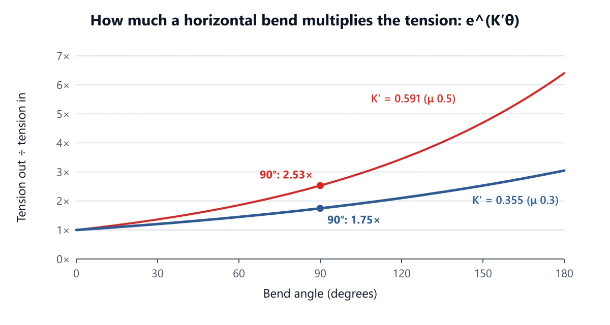
each bend multiplies the tension by e^(K′θ);
the result must stay below the cable's allowable pulling tension.
At every bend the cable is also pressed against the inside of the bend. That sidewall bearing pressure, roughly tension divided by bend radius, has its own limit.
This article sets out the IEEE Std 1185-2019 equations behind both checks and the weight correction factor that multiple cables add. It then works a real pull by hand, the same numbers the Cable Pulling Calculator gives, and shows what happens to that pull when the lubricant is skimped.
Why cable pulling tension matters
A cable that is overpulled may look fine on the drum end and still be damaged:
conductors stretched;
insulation thinned or cracked at a bend;
a sheath split where the cable was crushed against a sweep.
Damage like this tends to show up months later as an insulation fault, not on the day.
The fix is cheap at the design stage: a bigger conduit, a pit to split the pull, a gentler sweep, more lubricant, or pulling from the other end. Every one of those is expensive once the cable is in the ground. That is why we run the numbers on any pull with more than a couple of bends or more than a few tens of metres of conduit.
The cable pulling tension equations (IEEE 1185)
IEEE Std 1185-2019 is the IEEE recommended practice for cable installation in generating stations and industrial facilities. It works the route one section at a time. Each section's outgoing tension becomes the next section's incoming tension. The symbols:
W: total cable weight per metre, kg/m;
g: 9.8 m/s²;
L: section length, m;
μ: coefficient of friction (the calculator calls it K₀);
Wc: weight correction factor;
K′ = μ × Wc: the effective friction;
T₀: tension entering the section, N.
Straight sections
T = L × W × K′ × g + T₀ (Eq 5)
A straight adds tension in proportion to its length and the cable weight. It does not care how much tension is already there.
Slopes
T = W × g × L × (K′ cos α ± sin α) + T₀ (Eq 6a and 6b)
Use plus when pulling uphill and minus when pulling downhill. On a steep enough downhill, gravity beats friction and the result goes negative. The calculator then shows 0 N and flags the hold-back force the crew must apply.
Horizontal bends
T = T₀ × e^(K′θ) (Eq 7), with θ the bend angle in radians.
This is the capstan equation, and it is the one that catches people. A bend does not add a fixed amount; it multiplies whatever tension arrives. In the worked example below, the same 90° sweep adds about 740 N near the reel and about 3,060 N near the winch.
Vertical bends (dips and humps) have their own forms, IEEE 1185 Equations 9 to 12, because the cable's weight presses into or away from the bend. The calculator picks the right one from the route geometry.
Weight correction factor
One cable in a conduit rests on the bottom. Three cables wedge against each other and the wall, so the friction is higher than their weight alone suggests. IEEE 1185 accounts for this with the weight correction factor Wc, which multiplies μ. With D the conduit inside diameter and d the cable diameter:
three cables cradled (D/d above 3.0): Wc = 1 + 4/3 × (d ÷ (D − d))² (Eq 16);
three cables triangular (D/d below 2.5): Wc = 1 ÷ √(1 − (d ÷ (D − d))²) (Eq 17);
four cables, diamond: Wc = 1 + 2 × (d ÷ (D − d))² (Eq 18);
more than four cables: 1.4.
D/d is also the jam ratio. With three single cores, a D/d between 2.8 and 3.2 is the range where the cables can jam in a bend (IEEE 1185 clause 4.12), and the calculator warns when you are in it.
Sidewall bearing pressure
At a bend, the tension pulls the cable into the inside of the curve. The force per metre of bend is the sidewall bearing pressure (SWBP):
one cable: P = T ÷ R (Eq 19);
three cables cradled: P = (3Wc − 2) ÷ 3 × T ÷ R (Eq 20). The bottom cable carries most of the load.
three cables triangular: P = Wc × T ÷ (2R) (Eq 21).
Here R is the bend radius in metres and T the tension leaving the bend.
Two things follow. SWBP is worst at the last bend, where tension is highest. And halving the bend radius doubles it. Use the tightest sweep on the route as the radius, and never go below the cable's minimum bending radius. Our post on the minimum bend radius of cables covers that limit.
What is the allowable pulling tension?
Take the maximum pulling tension per cable from the manufacturer's datasheet. It depends on the conductor and on how the cable is gripped (pulling eye on the conductors, or a stocking grip on the sheath).
When several cables are pulled together they do not share the load evenly. The calculator follows common industry practice:
one or two cables: the single-cable limit × the number of cables;
three cables: × 2;
four or more: × 0.8 × the number.
With different cables in the same pull, it uses the lowest single-cable limit. Take the sidewall pressure limit from the datasheet too. The calculator starts at 7,300 N/m, a common figure for power cables, but the manufacturer's value governs.
Worked example: a 210 m pull with two bends
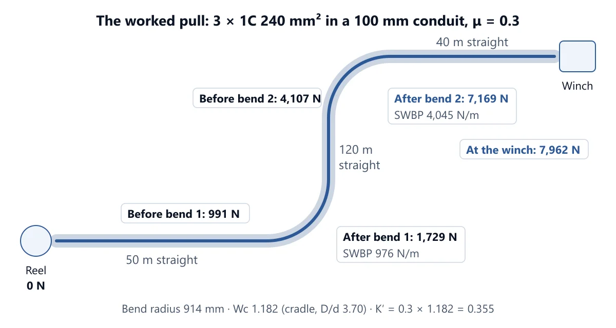
The pull: three single-core 240 mm² XLPE cables, each 27 mm in diameter and 1.9 kg/m, rated 6.7 kN maximum tension and 7,300 N/m sidewall pressure. They go through a 100 mm (bore) conduit with 914 mm radius sweeps.
The route from the reel: 50 m straight, 90° bend, 120 m straight, 90° bend, 40 m straight to the winch. The conduit is lubricated, μ = 0.3, and there is no back tension at the reel.
Step 1: weight correction
D/d = 100 ÷ 27 = 3.70, so the cables cradle (Eq 16).
Wc = 1 + 4/3 × (27 ÷ 73)² = 1.182
K′ = 0.3 × 1.182 = 0.355
The total weight is W = 3 × 1.9 = 5.7 kg/m.
Step 2: first straight
T₁ = 50 × 5.7 × 0.355 × 9.8 = 991 N
Step 3: first bend
90° is 90 × 0.01745 = 1.5705 rad, and e^(0.355 × 1.5705) = 1.746.
T₂ = 991 × 1.746 = 1,729 N
SWBP = (3 × 1.182 − 2) ÷ 3 × 1,729 ÷ 0.914 = 976 N/m
Step 4: long straight
T₃ = 120 × 5.7 × 0.355 × 9.8 + 1,729 = 4,107 N
Step 5: second bend
T₄ = 4,107 × 1.746 = 7,169 N
SWBP = 0.516 × 7,169 ÷ 0.914 = 4,045 N/m
Step 6: last straight
T₅ = 40 × 5.7 × 0.355 × 9.8 + 7,169 = 7,962 N
Step 7: compare with the limits
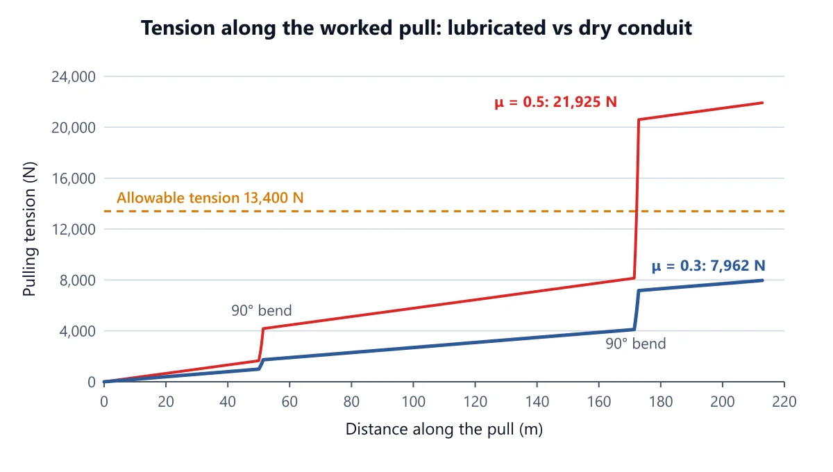
The allowable tension for three cables is 6.7 kN × 2 = 13,400 N.
Peak tension: 7,962 N, 59% of 13,400 N.
Worst sidewall pressure: 4,045 N/m at the second bend, 55% of 7,300 N/m.
The pull passes both checks.
Notice where the tension comes from. The two straights after the first bend add the same amount per metre wherever they are. The second bend, though, adds 3,062 N, more than four times the first bend's 739 N, purely because it comes later in the pull.
The same pull with dry conduit
Change only μ to 0.5, the calculator's "rough / dirty conduit" preset. K′ becomes 0.591, and each 90° bend now multiplies the tension by 2.53 instead of 1.75. The pull peaks at 21,925 N with 11,626 N/m at the second bend. It fails both limits by a wide margin.
Two other levers are worth knowing. A 125 mm bore conduit lowers Wc to 1.101 and the peak to 7,063 N. Going down to an 85 mm bore raises the peak to 9,260 N, and its D/d of 3.15 sits in the jam range. And 1,000 N of back tension at the reel, from a braked drum, turns into 3,047 N at the winch after the two bends, giving 11,009 N.
Common mistakes
Adding bends instead of multiplying. Treating a bend as a fixed allowance badly understates tension late in a pull.
Using the cable count × the single-cable rating. Three cables do not share the pull evenly. Take twice the single-cable limit, not three times.
Forgetting the weight correction. Three cables in a snug conduit have noticeably more friction than one; Wc was 1.18 here and 1.29 in an 85 mm conduit.
Checking tension but not sidewall pressure. A pull can be within its tension limit and still crush the cable at a tight bend near the end.
Using the nominal conduit size. Wc and the jam ratio use the bore. Enter the inside diameter.
Assuming the lubricant. If nobody on site has committed to lubricating the pull, work it at 0.5 as well.
FAQ
How do you calculate cable pulling tension?
Start at the reel with the back tension. Add L × W × K′ × g for each straight, add or subtract the weight component on slopes, and multiply by e^(K′θ) at each bend. The tension leaving the last section is the pulling tension at the winch. Compare it with the cable's allowable tension.
What is a safe sidewall bearing pressure?
It is the cable manufacturer's figure. Many power cable datasheets give values in the region of the calculator's 7,300 N/m starting value, but some cables are rated lower, so always check.
What coefficient of friction should I use?
Use the lubricant manufacturer's figure for your cable jacket and conduit where you have it. Lubricated pulls are commonly worked at 0.2 to 0.5, and the calculator starts at 0.3. If in doubt, check that the pull still passes at 0.5.
Does the direction of pull matter?
Yes. Bends near the winch end multiply a larger tension. For this route the reverse pull peaks at 7,556 N instead of 7,962 N, a small gain because the bends sit near both ends. On routes with all the bends at one end, the difference can decide whether the pull is possible. The calculator works both directions from one route.
Check your pull before the crew arrives
Open the Cable Pulling Calculator and enter:
the cables: diameter, kg/m, quantity, and the maximum tension and sidewall pressure from the datasheet;
the conduit bore and the tightest bend radius;
the route, straight by straight and bend by bend, in pull order.
Read the peak tension and worst sidewall pressure, then switch to μ 0.5 and to the reverse direction to see your margin. You can download the result as a PDF for the installer.
For the cable size itself, see our guide to the free electrical calculators. For the conduit fill, see the conduit calculator guide.
Work it out for your circuit
Free calculators, no sign-up needed.
Related articles
Continue reading more articles on this topic.
Industry KnowledgeSuheib
Power Factor Correction: How to Size a Capacitor Bank in kVAr
The kVAr a capacitor bank needs comes from one formula, but the steps, the targe…
Read more: Power Factor Correction: How to Size a Capacitor Bank in kVAr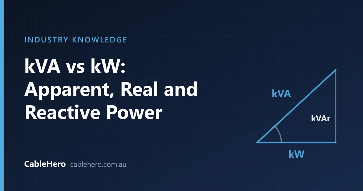
Industry KnowledgeAhmed Tayeh
kVA vs kW: Apparent, Real and Reactive Power Explained for Electricians
kW is the power that does the work, kVA is what the cables and transformers have…
Read more: kVA vs kW: Apparent, Real and Reactive Power Explained for Electricians
Industry KnowledgeAhmed Tayeh
kW to Amps: How to Convert Kilowatts to Amps for Single-Phase, Three-Phase and DC
The kW to amps formulas for single-phase, three-phase and DC supplies, why the p…
Read more: kW to Amps: How to Convert Kilowatts to Amps for Single-Phase, Three-Phase and DC