Almost every Australian electrician and designer can quote the "5% rule" for voltage drop without hesitation. Far fewer can explain exactly where that figure comes from, how it's meant to be allocated across an installation, or what happens when a design genuinely can't meet it.
Voltage drop compliance gets treated as a simple pass or fail check, when it's actually a design constraint with real engineering judgement built into how the standard applies it.
This guide covers what AS/NZS 3000 actually requires for voltage drop, how the limit works in practice, and where designers most commonly get it wrong.
Why Do Voltage Drop Limits Exist?
Every conductor carrying current has resistance, and that resistance causes voltage to fall progressively along the length of a cable run.
By the time electricity reaches a piece of equipment at the far end of a long circuit, the voltage available to that equipment can be measurably lower than the voltage at the point of supply.
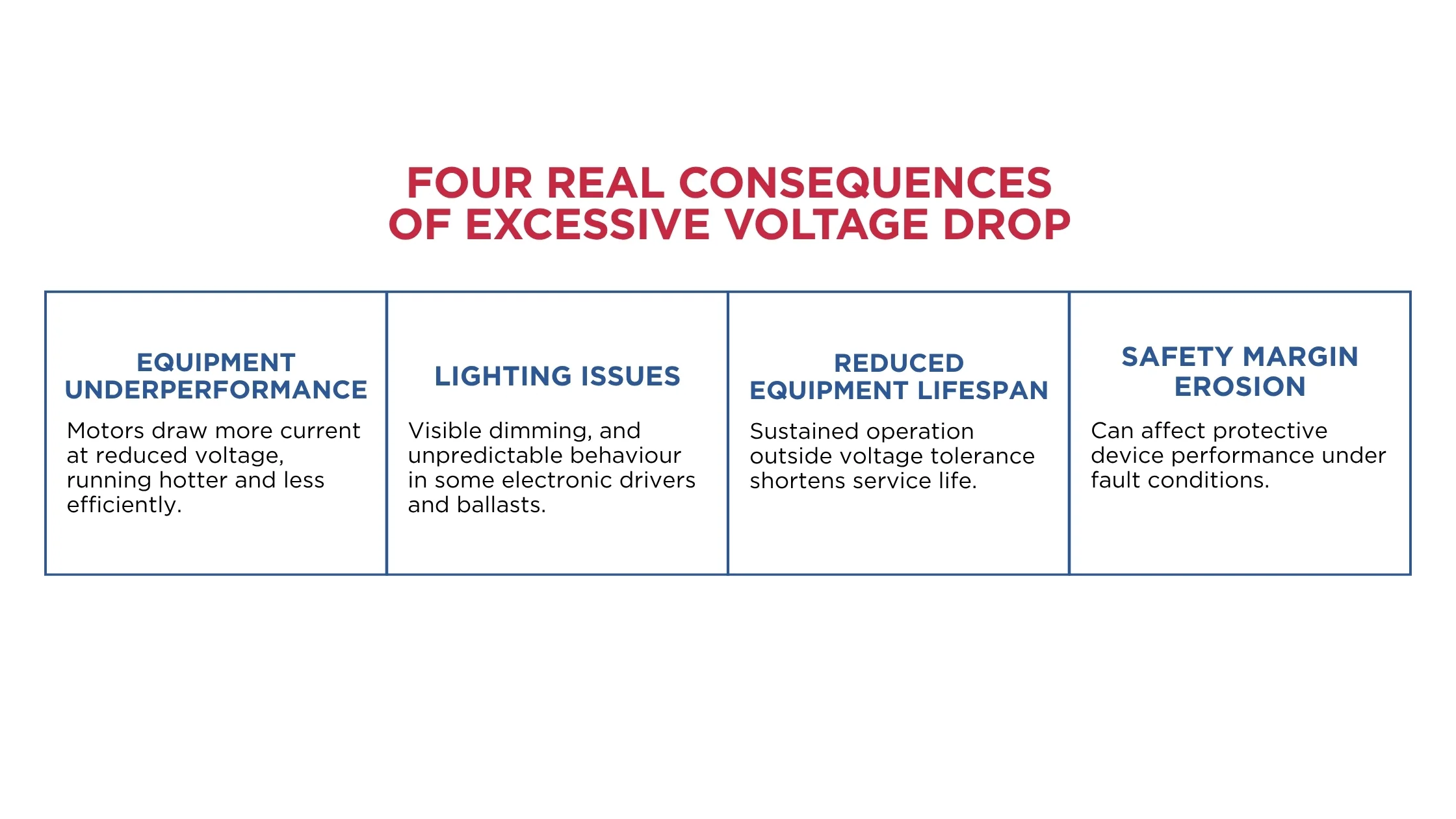
Excessive voltage drop causes real, practical problems.
- Equipment Underperformance: Motors draw more current at reduced voltage to deliver the same output, running hotter and less efficiently, and in some cases failing to start correctly at all.
- Lighting Issues: Incandescent and some other lighting types visibly dim under excessive voltage drop, while certain electronic lighting drivers and ballasts can behave unpredictably outside their designed voltage range.
- Reduced Equipment Lifespan: Many electrical and electronic devices are designed to operate within a specific voltage tolerance, and sustained operation outside that range can shorten their service life.
- Safety Margin Erosion: Voltage drop calculations exist alongside other safety-critical figures like fault loop impedance, and excessive drop can affect how a protective device performs under fault conditions at the far end of a circuit.
Voltage drop limits in AS/NZS 3000 exist specifically to keep these effects within an acceptable, predictable range across any compliant installation.
What Is the General Rule?
AS/NZS 3000 sets a general voltage drop limit of 5% of the nominal voltage, measured from the point of supply to any point in the electrical installation.
For a standard 230V single-phase supply, this means voltage drop should not exceed approximately 11.5V under the design load conditions, with the equivalent percentage applied for three-phase installations at their respective nominal voltage.
This 5% figure is a total allowance across the entire electrical path, not a limit applied separately and in full to every individual section of cable. In practice, that overall allowance needs to be sensibly divided between the different stages of an installation.
- From the point of supply to the main switchboard (the consumer mains or service main)
- From the main switchboard to a sub-board (the sub-main, where one exists)
- From the sub-board or main switchboard to the final piece of equipment
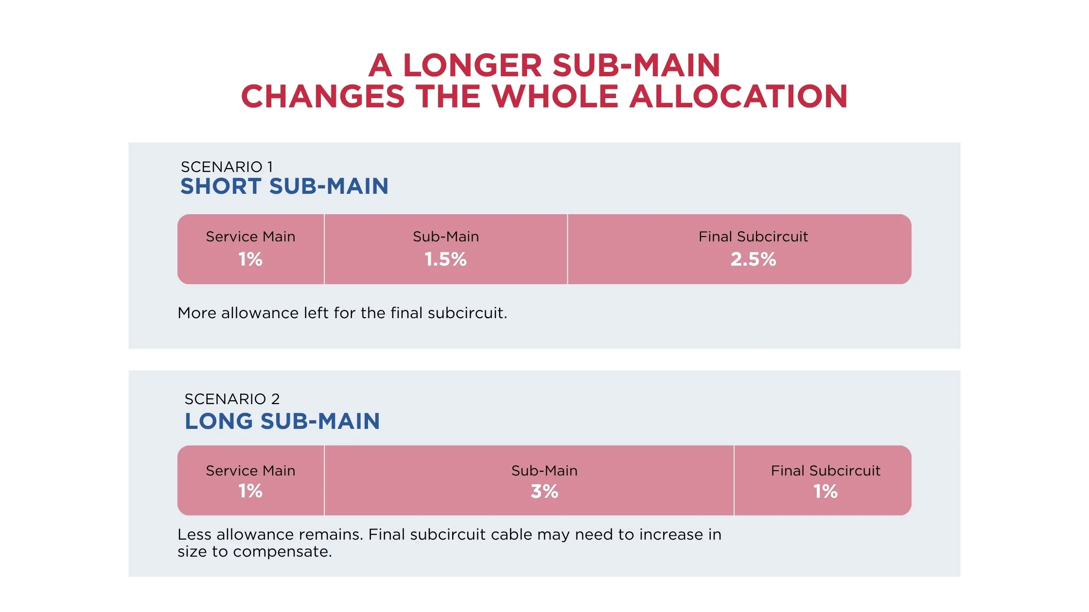
How this 5% is split between these stages is a design decision. A short service main and a long sub-main run might reasonably allocate more of the total allowance to the sub-main. A design without any sub-main at all simplifies the allocation to just two stages.
The key requirement is that the combined voltage drop across every stage in a single circuit's path stays within the overall 5% limit.
When a Different Limit Applies
While 5% is the general rule most designers work to, AS/NZS 3000 does allow for specific circumstances where a different voltage drop outcome may be acceptable, provided it can be properly justified and documented.
This typically applies where a designer can demonstrate that a higher voltage drop on a specific part of an installation won't compromise the safe and effective operation of the equipment.
It's a recognition that
voltage drop compliance should ultimately be about ensuring equipment operates safely and as intended. The standard allows for documented engineering judgement in the specific situations where a strict percentage figure doesn't fully capture that intent. Any departure from the standard 5% limit needs to be clearly justified and documented, not simply assumed or applied without a defensible technical basis.
How Is Voltage Drop Calculated?
Voltage drop is calculated using a cable's resistance and, for larger installations, reactance values, combined with the circuit's current and length.
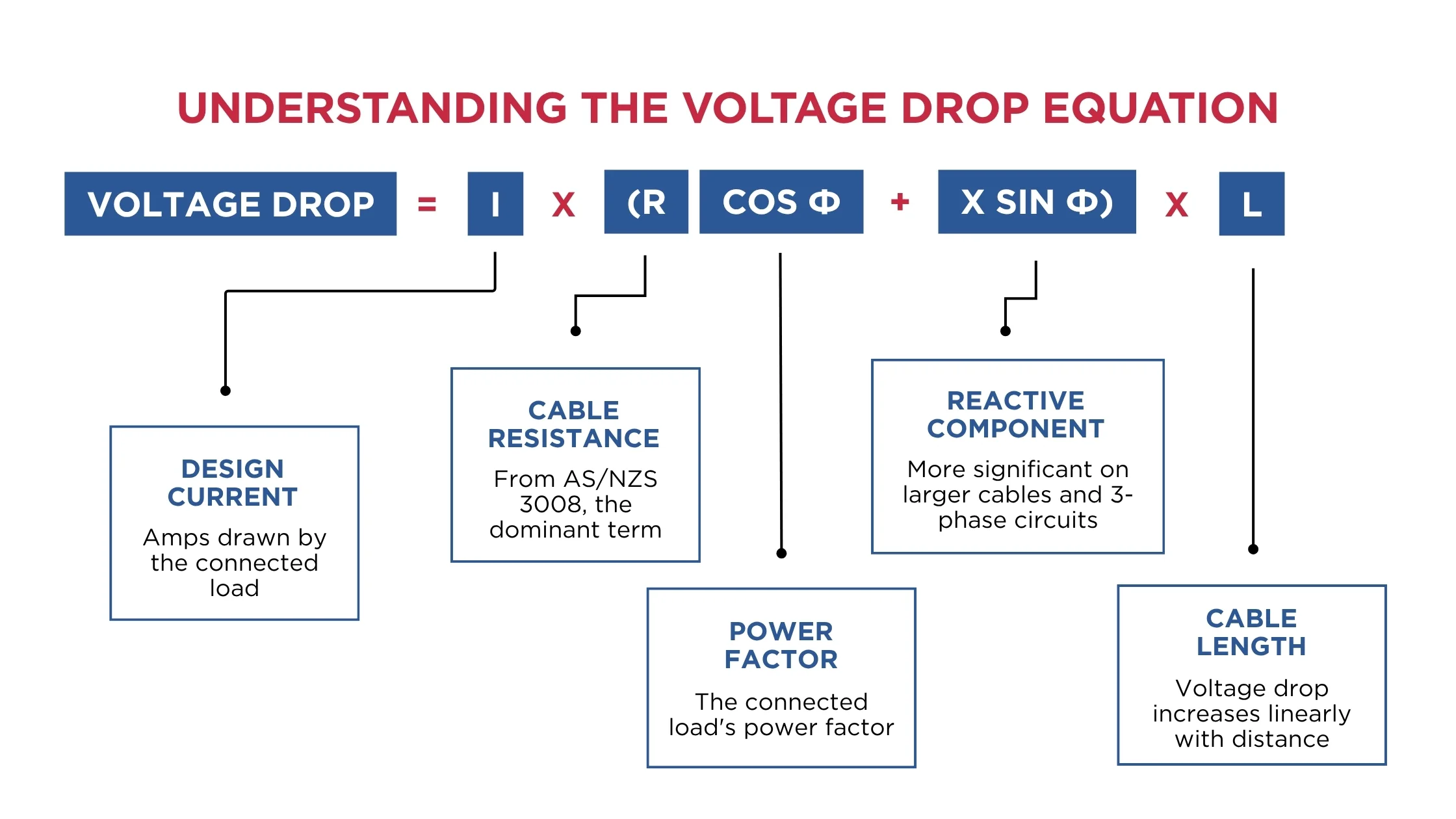
The general form of the calculation is: Voltage Drop (V) = I × (R cos φ + X sin φ) × L
- I = Design Current (amps)
- R = Cable Resistance (ohms per unit length)
- X = Cable Reactance (ohms per unit length, more significant on larger cables and three-phase circuits)
- cos φ = Power Factor of the Connected Load
- L = Cable Length
For most standard commercial and residential circuits at typical power factors, the resistive term dominates the result, making cable size, and by extension, cable resistance, one of the most direct ways to manage voltage drop within a design.
Practical Voltage Drop Allocation Across a Real Installation
Consider a typical commercial installation:
- A service main from the point of supply to the main switchboard
- A sub-main from the main switchboard to a floor distribution board
- A final subcircuit from that board to a piece of equipment
A sensible allocation might reserve a smaller share of the total 5% for the service main. These runs are often relatively short, while allowing a larger share for the sub-main, particularly where it runs a significant distance to reach a distant part of a building or site. The final subcircuit then needs to work within whatever allowance remains.
This is exactly why sub-main sizing on longer commercial runs so often becomes the deciding factor in overall compliance. If a service main consumes more of the 5% allowance than planned, the remaining sub-main and final subcircuit have less room to work with, and cable sizes further down the chain may need to increase to compensate.
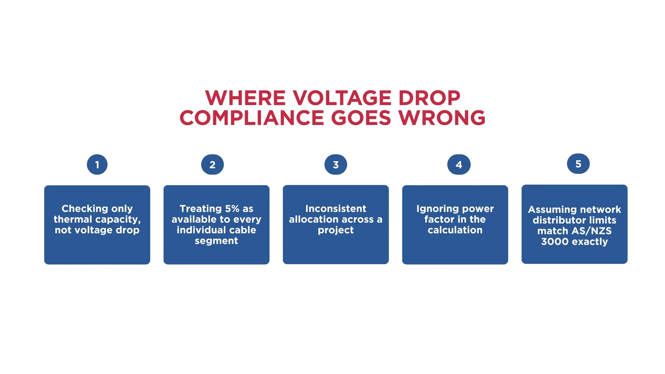
What Are the Common Mistakes with Voltage Drop Compliance?
- Checking Only Thermal Capacity: A cable correctly sized for current-carrying capacity can still fail voltage drop compliance on a longer run, since the two checks address different physical limits.
- Treating 5% as Available to Every Individual Cable Segment: The 5% is a total allowance across the full circuit path, not a separate 5% budget for the service main, the sub-main, and the final subcircuit each.
- Inconsistent Allocation Across a Project: Without a clear, documented voltage drop allocation strategy applied consistently, different designers or different circuits on the same project can end up with inconsistent, and sometimes incompatible, allowances.
- Ignoring Power Factor in the Calculation: Using a generic assumed power factor rather than the actual connected load's power factor can produce a voltage drop result that doesn't accurately reflect real operating conditions.
- Assuming Network Distributor Limits Match AS/NZS 3000 Exactly: Some network distributors apply their own, sometimes more conservative, voltage-related requirements at the point of connection, separate from AS/NZS 3000's own limit, and these need to be checked specifically rather than assumed identical.
Calculate Voltage Drop Correctly with CableHero
Manually allocating a 5% voltage drop budget across service mains, sub-mains, and final subcircuits, then checking each stage against AS/NZS 3008 cable data, is a genuinely detailed process. A small miscalculation can produce a non-compliant result further down the circuit.
CableHero's cable sizing platform calculates voltage drop alongside current-carrying capacity and derating in the same workflow, using the actual cable parameters, length, and load for every stage of a circuit. Every result generates a clear, documented report showing exactly how the voltage drop allowance has been allocated and met, ready to support a compliance certificate or a network distributor's review.
For engineers managing voltage drop across multi-stage commercial, industrial, or renewable energy installations, that consistency turns a detail-heavy manual process into a fast, defensible part of the design.
FAQ
Is the 5% voltage drop limit applied separately to the service main, sub-main, and final subcircuit?
No. The 5% limit under AS/NZS 3000 is a total allowance across the entire circuit path, from the point of supply to the final point of use. It needs to be sensibly divided between the different stages of the installation, service main, sub-main, and final subcircuit, so that the combined voltage drop across all stages together stays within the overall 5% limit, not 5% at each individual stage.
Can a design ever exceed the 5% voltage drop limit and still be compliant?
In specific, properly justified circumstances, yes, AS/NZS 3000 allows for documented engineering judgement where a higher voltage drop can be shown not to compromise the safe and effective operation of the connected equipment. This isn't a general exception, though, and any departure from the standard 5% limit needs clear technical justification and documentation, not just convenience or an unchecked assumption.
Why does voltage drop matter more on longer commercial and industrial cable runs?
Voltage drop increases with cable length, so longer runs, common in larger commercial buildings, industrial sites, and renewable energy projects, are far more likely to require a larger cable size than thermal current-carrying capacity alone would suggest. On these longer runs, voltage drop frequently becomes the deciding factor in final cable size, rather than a secondary check performed after thermal sizing is already settled.


 Cable Sizing