Single Line Diagram for Commercial Buildings: A Step-by-Step Guide
13Oct
Ahmed Tayeh
Industry Knowledge
Single Line Diagram for Commercial Buildings: A Step-by-Step Guide
Every commercial electrical installation starts with one drawing: the single line diagram. It's the document that shows how power flows from the main supply through switchboards, distribution boards, and out to the loads across the building.
For anyone reviewing, approving, or maintaining the electrical system, the single line diagram (SLD) is often the first thing they look at as the clearest reference point on the whole project.
This guide walks through what a single line diagram actually needs to show for a commercial building, how to draw one step by step, and where people commonly go wrong.
What Is a Single Line Diagram?
A single line diagram is a simplified representation of an electrical system. Instead of showing every individual conductor the way a full wiring diagram does, it uses a single line to represent each circuit, along with standard symbols for switchboards, protective devices, and loads.
The goal is to show the electrical relationship between components: how power is distributed, protected, and switched throughout the building, from the point of supply down to individual distribution boards. For a commercial building, the SLD typically needs to show:
The point of supply and incoming service details (voltage, phases, supply capacity)
Main switchboard (MSB) and its protective devices
Sub-boards and distribution boards throughout the building
Any standby or backup power sources, such as generators or UPS systems
Load descriptions for major circuits
Why Does the Single Line Diagram Matter for Commercial Buildings?
Commercial buildings carry more electrical complexity than residential properties. Multiple tenancies, larger loads, backup power requirements, and multi-level distribution all need to be represented clearly on one drawing.
The SLD serves several purposes across a project's life:
Design Verification: It's used to confirm that protective devices are correctly coordinated, and that cable sizing and switchboard capacity match the building's load.
Regulatory and Compliance Review: Certifying authorities and network distributors reference the SLD when assessing a new connection or a significant upgrade.
Construction Reference: Contractors on site use it to understand how the system is meant to be connected and protected.
Ongoing Maintenance: Facility managers and electricians rely on it for years after handover, whenever fault-finding, upgrades, or maintenance work is needed.
An SLD that's inaccurate or out of date doesn't just cause confusion during design. It creates risk every time someone opens it later to understand how the building's power system works.
What Are the Standard Symbols Used in a Single Line Diagram?
Consistency matters as much as accuracy. Using standard, recognisable symbols means anyone in the industry can pick up the drawing and understand it immediately. C19.2.webp247.3 KB
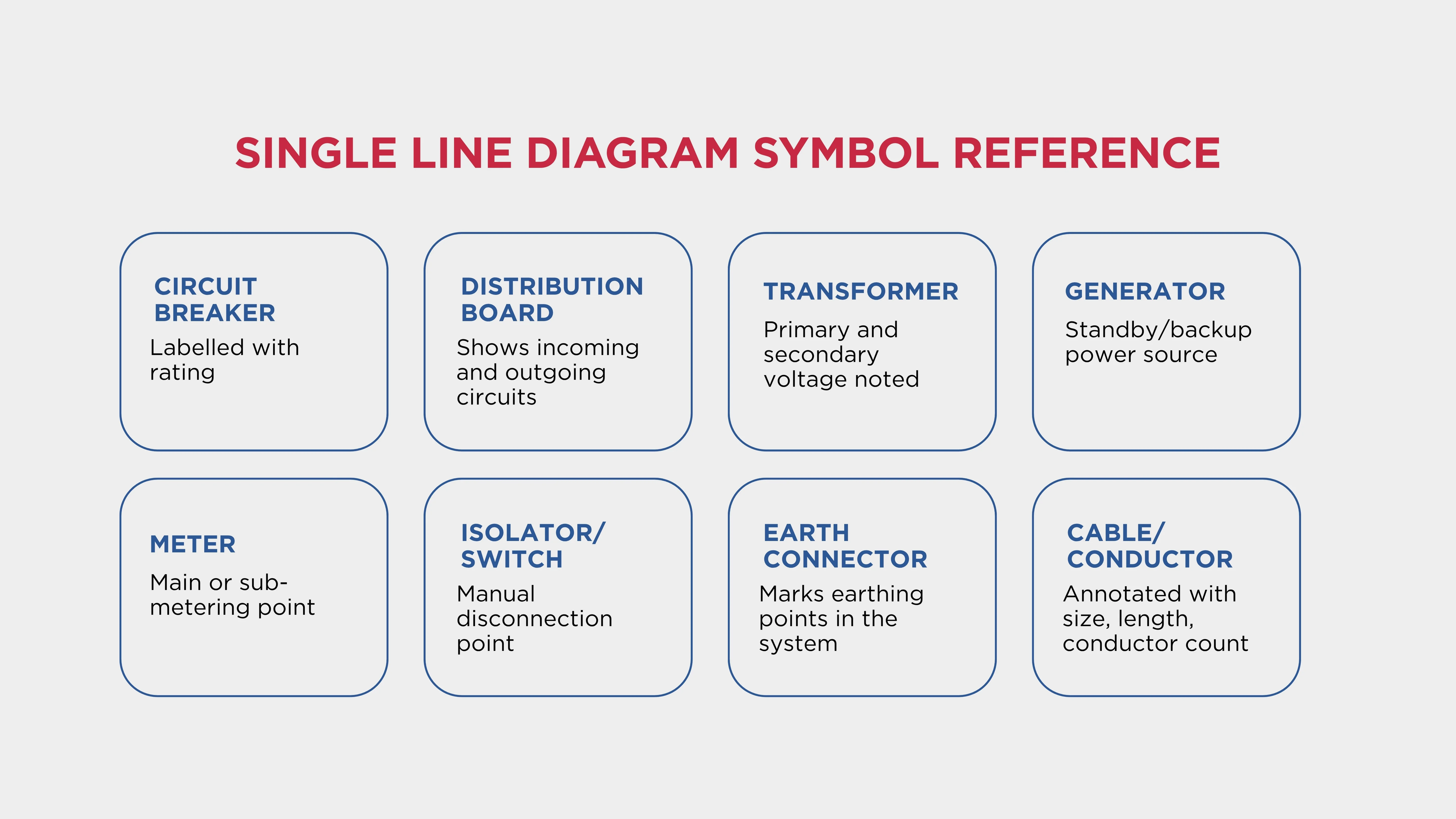
Common symbols include:
Circuit Breaker: A labelled rectangle or specific breaker symbol, with rating noted alongside
Switchboard/Distribution Board: A labelled box, typically showing incoming and outgoing circuits
Transformer: Two overlapping circles, with primary and secondary voltage noted
Generator: A circle with a "G" designation
Meter: A circle with an "M" or "kWh" designation
Isolator/Switch: A simple line break symbol
Earth Connection: A standard earthing symbol at relevant points
Cable/Conductor: A single line, annotated with size, length, and number of conductors
Every symbol should be labelled clearly, and a legend should accompany the drawing if any non-standard symbols are used.
How Is a Single Line Diagram Drawn for a Commercial Building?
Step 1: Confirm the Point of Supply. Start with the incoming supply: voltage, number of phases, and the capacity agreed with the network distributor. This becomes the top of the diagram, everything else flows from it.
Step 2: Draw the Main Switchboard. Represent the main switchboard (MSB) directly below the point of supply, including the main protective device and metering arrangement.
Step 3: Map Out Distribution Levels. For a commercial building, this usually means sub-boards on each floor or tenancy, feeding down from the MSB. Each sub-board should be drawn with its own protective device connected back to its supply point.
Step 4: Add Circuit Details for Each Board. For every outgoing circuit from a board, note the cable size, cable length, protective device rating, and a brief load description.
Step 5: Include Standby and Backup Power. If the building has a generator, UPS, or any alternative supply, show how it connects into the system, including any automatic transfer switches and which loads it's designed to support.
Step 6: Show Metering and Monitoring Points. Mark where main and sub-metering occurs, particularly important in multi-tenancy commercial buildings where individual tenants are billed separately.
Step 7: Add a Legend and Title Block. Every SLD needs a legend explaining any symbols used, along with a title block noting the project name, revision number, date, and the designer responsible.
Step 8: Review for Protection Coordination. Before finalising, check that protective devices are correctly coordinated: upstream devices should be rated to protect downstream equipment without unnecessary nuisance tripping, and fault levels should be considered at each point in the system.
What Are Common Mistakes to Avoid?
Missing Cable and Circuit Details: An SLD that only shows boards and breakers without cable sizes or lengths isn't much use for verification or maintenance later.
Inconsistent Symbols: Mixing standard and non-standard symbols without a clear legend makes the drawing harder for anyone outside the original design team.
Ignoring Protection Coordination: A visually complete SLD that hasn't actually been checked for correct device coordination can look right while hiding a real safety issue.
Outdated Revisions in Circulation: In a commercial project, the SLD often changes as the design develops. Without clear revision control, contractors on site can end up working from a version that no longer matches the approved design.
Overcomplicating the Drawing: An SLD should stay legible. Cramming too much detail into one sheet, rather than splitting a large commercial building into multiple linked diagrams by level or zone, makes the whole document more error-prone.
Single Line Diagrams for Simple vs Complex Commercial Buildings
A small commercial tenancy fit-out might need only a single-page SLD, covering one switchboard and a handful of circuits. A larger commercial building, multi-storey office, retail complex, or facility with embedded generation, is a different scale of drawing entirely.
For these larger projects, it's common to split the SLD across multiple sheets, one for the main switchboard and overall building distribution, and separate sheets for each major sub-board or tenancy. Cross-references between sheets need to be clear, so anyone following the system from the point of supply down to a specific circuit can trace it without confusion.
Draw and Manage Single Line Diagrams Faster with CableHero
Drawing an SLD by hand or in general-purpose drafting software works, but it's slow, and keeping it consistent with standard electrical symbols takes extra care.
CableHero's Single Line Diagram tool is built specifically for this task.
It gives you a drag-and-drop editor with a library of professional, industry-standard electrical symbols, so switchboards, protective devices, transformers, and loads are represented correctly without redrawing them from scratch. Diagrams export cleanly to PDF or SVG, ready to attach to a compliance submission or issue to a contractor, and real-time collaboration means your team can work on the same diagram together instead of passing files back and forth.
Because CableHero connects cable sizing, maximum demand, and SLD drawing in one platform, the circuit details on your diagram, cable sizes, lengths, and protective device ratings, can be pulled directly from your existing calculations, rather than transcribed by hand and risking a mismatch between the drawing and the design.
Start your free trial with CableHero and draw your next commercial single line diagram with the right symbols, consistent formatting, and your calculations built in from the start.
FAQ
What's the difference between a single line diagram and a wiring diagram?
A single line diagram simplifies the electrical system into single lines and standard symbols, showing how power is distributed and protected. A wiring diagram, by contrast, shows the actual physical wiring, including every individual conductor and its routing. Commercial buildings typically need both, but the SLD is the primary reference for understanding how the system is designed to work.
Does every commercial building need a single line diagram?
Yes. Any commercial electrical installation with a switchboard and multiple distribution points needs an SLD, both for design verification and for network distributor or certifying authority review. Even a small commercial tenancy fit-out generally needs at least a simple, single-page SLD covering its switchboard and circuits.
How often should a commercial building's single line diagram be updated?
The SLD should be updated any time the electrical system changes, whether that's a new sub-board, an added generator, or a significant load change. Facility managers should treat an out-of-date SLD as a real risk, since it's often the first document referenced during fault-finding or future upgrade work.


 Industry Knowledge