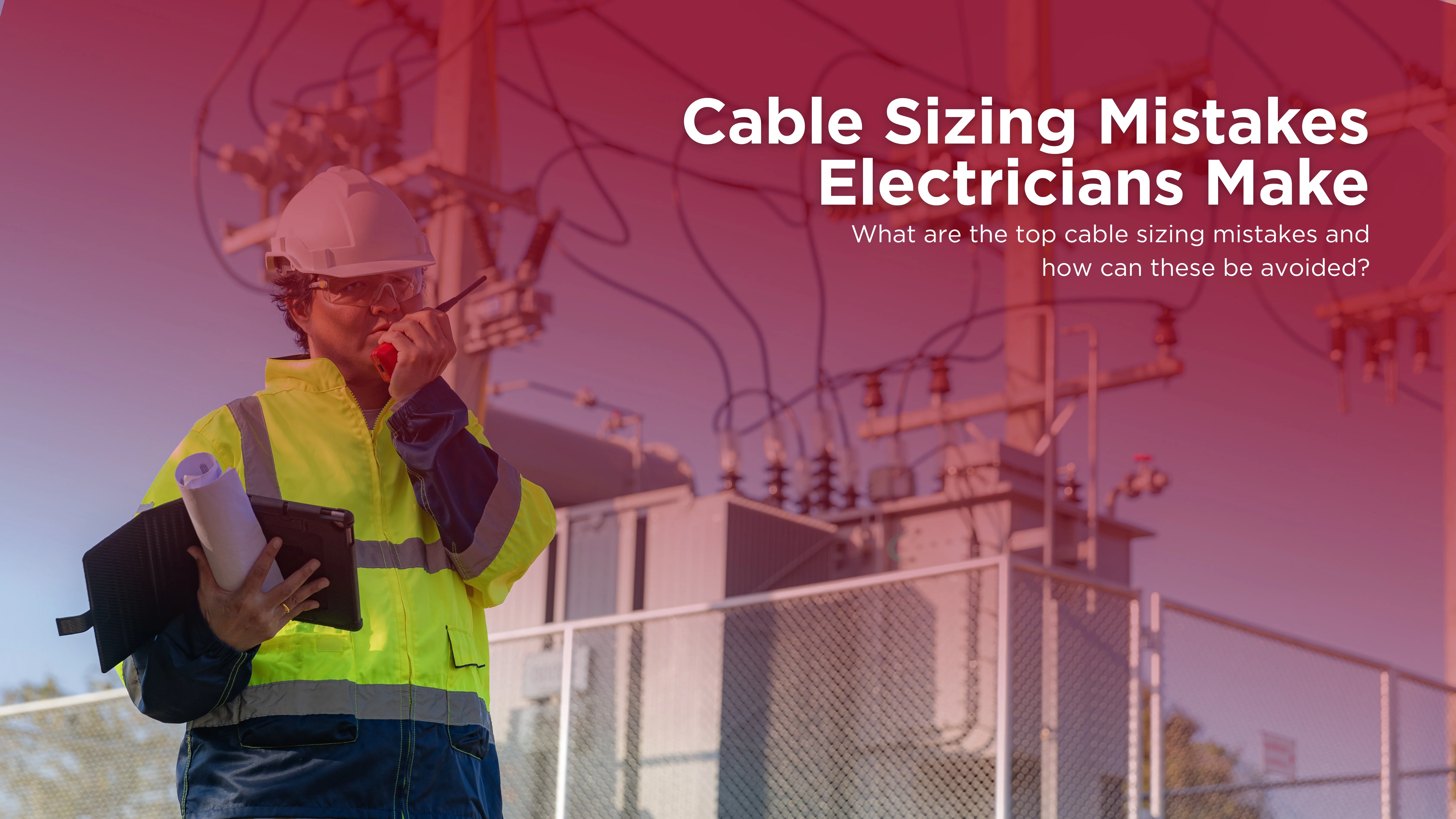
How Cable sizing looks straightforward. You have a load, a length, an installation method, and a standard to follow. However, between tables, stacked correction factors, and voltage drop limits, the margin for error is real.
The consequences of getting it wrong are serious. The good news? Most cable sizing mistakes follow predictable patterns.
The same errors come up again and again across residential, commercial, and industrial installations. And knowing what they are is the first step to eliminating them. Here are the ten most common cable sizing mistakes Australian electricians make, and how to avoid each one.
Using Base Current Ratings Without Applying Correction Factors
This is the most common and dangerous cable sizing mistake. AS/NZS 3008 current rating tables are based on specific baseline conditions:
- 40°C ambient temperature for cables in air
- 25°C ground temperature for buried cables
If your installation conditions differ from those baselines, the cable’s effective current-carrying capacity must be reduced.
Correction factors apply for:
- Ambient temperature above 40°C (Table 27 — AS/NZS 3008:2025)
- Multiple cables grouped together in conduit or bundles (Table 22)
- Burial depth exceeding 0.5 m (Table 28)
- High soil thermal resistivity for buried cables (Table 29)
Applying the base rating without these corrections means the cable will operate above its rated temperature under load. This accelerates insulation degradation and raises fire risk.
How to Avoid This
- Identify all applicable correction factors before selecting a cable size.
- Multiply them together to find the derated current capacity, then select the cable that meets or exceeds that derated value.
If you’re using cable sizing software like
CableHero, confirm it applies all relevant factors automatically.
Ignoring Voltage Drop on Long Cable Runs
Current-carrying capacity is only one of the three tests a cable must pass. Voltage drop is the second, and on long cable runs, it is often the controlling criterion.
AS/NZS 3000 Clause 3.6 sets a maximum voltage drop of 5% from the point of supply to any equipment. In practice, this is typically split as 2% for the consumer mains and 3% for final sub-circuits.
A cable that passes the current-carrying capacity check can still fail on voltage drop for runs exceeding 20-30 metres at smaller cross-sections. For every 1% of voltage drop in solar PV string cables, approximately 1% of energy is lost over the system lifetime.
How to Avoid This
- Always run the voltage drop calculation, even on circuits that comfortably pass the current check.
- Use the formula Vd = 2 × I × L × Zc ÷ 1000 for single-phase circuits (multiple active and neutral), or the equivalent three-phase formula.
If voltage drop exceeds the limit, upsize the cable.
Selecting the Wrong Installation Method Table
AS/NZS 3008 contains multiple current rating tables, each corresponding to a specific installation method. Selecting the wrong table results in a cable that is effectively undersized for its actual installation.
The most common error here is using the “clipped direct” or “free air” rating for cables that will be pulled through conduit inside a wall or ceiling space. Cables in conduit have significantly reduced heat dissipation. Therefore, they have a lower current-carrying capacity than cables clipped to a surface or installed in free air.
How to Avoid This
- Confirm the exact installation method before looking up any table.
A cable run that changes method partway must be rated for the most restrictive section.
Forgetting to Check Short-Circuit Withstand Capacity
Short-circuit withstand is the third test every cable must pass and the most frequently skipped. This particularly applies on smaller commercial and residential installations.
The check verifies that the cable can handle the thermal energy produced by a fault current during the time it takes the protective device to clear the fault. For cables close to the main switchboard where fault levels are highest, this check is critical.
The adiabatic equation from AS/NZS 3008 Clause 5 is: S = (I × √t) ÷ K.
- S is the minimum conductor cross-section in mm²
- I is the prospective short-circuit current
- t is the fault clearing time
- K is a constant based on conductor material and insulation type
How to Avoid This
- Obtain the prospective short-circuit current from the network provider or calculate it from the supply impedance.
- Run the adiabatic equation for every cable, particularly those directly connected to the switchboard.
Upsize if the minimum calculated size exceeds the size selected for current-carrying capacity and voltage drop.
Sizing the Earth Conductor by Assumption
Many electricians default to matching the earth conductor to the active. Some select whatever size “feels right” without even checking AS/NZS 3000 Table 5.1.
Earth conductor sizing has two requirements that must both be satisfied:
- The minimum size from AS/NZS 3000 Table 5.1 based on the active conductor size.
- A short-circuit withstand check for the phase-to-earth fault current during the protective device clearing time.
A common mistake is undersizing the earth on larger circuits. For example, a 25 mm² active conductor requires a minimum 10 mm² earth per AS/NZS 3000 Table 5.1 — not 6 mm².
How to Avoid This
- Always reference AS/NZS 3000 Table 5.1 for the minimum earth size.
- Verify that the selected earth can withstand the phase-to-earth fault current.
Both conditions must be satisfied, and the larger of the two results governs.
Not Accounting for Roof Space Temperature
In Australian summers, roof spaces routinely reach 60–70°C. The AS/NZS 3008 baseline assumption of 40°C ambient temperature no longer applies. Ignoring this is one of the most common cable sizing mistakes in residential installation.
For example:
A cable correctly sized for 40°C ambient that is installed in a 60°C roof space is operating in conditions it was not sized for. The correction factor for 60°C ambient applied to a PVC-insulated cable drops the effective current-carrying capacity to approximately 67% of the base rating.
How to Avoid This
- Determine the realistic maximum ambient temperature for every section of a cable run.
- Apply the corresponding temperature correction factor from AS/NZS 3008 Table 27.
Applying the Wrong Grouping Factor
When multiple circuits share the same conduit, cable tray, or bundle, they generate collective heat that each cable can’t dissipate as efficiently. The grouping correction factor reduces the current-carrying capacity of all cables in the group.
The mistake comes in two forms:
- Forgetting to apply a grouping factor at all
- Applying the wrong factor by miscounting the number of circuits
A common scenario: a four-circuit conduit run is sized as if each cable were in individual conduit. Then, the circuits are bundled together on-site without any capacity reduction.
The grouping correction factor for cables in a conduit or touching can drop as low as 0.65 for six cables and 0.55 for more than six.
How to Avoid This
- Count the actual number of current-carrying conductors sharing the same enclosure or bundle.
- Apply the correct factor from AS/NZS 3008 Table 22.
If grouping substantially reduces capacity, consider splitting circuits into separate conduits or increasing cable size.
Ignoring the AS/NZS 3008 Update for DC Cable Sizing
Before AS/NZS 3008.1.1:2025, there was no dedicated Australian standard table for DC cable sizing. Engineers and electricians had to adapt AC tables using:
- Manual corrections
- IEC guidance
- Manufacturer data
None of these carried the authority of the national standard. The 2025 edition introduces DC cable rating tables (Tables 3.21 and 3.22) for systems up to 1500 V DC for the first time.
How to Avoid This
- Familiarise yourself with the new DC cable tables in AS/NZS 3008.1.1:2025.
- Apply the new methodology, for solar PV string cables, battery-to-inverter DC cables, and EV charger fixed wiring.
If you use
cable sizing software, confirm it has been updated to include the 2025 DC tables. For CableHero, we’ve recently updated our software according to the new standards.
Treating Voltage Drop as a Single-Cable Check
Voltage drop is a cumulative calculation. It must account for the total drop from the point of supply to the load, across every cable section in series.
A common mistake is checking voltage drop on the final sub-circuit but not including the drop across the consumer mains or sub-main. If the consumer mains already consumes 2% and the sub-circuit adds another 4%.
- The total of 6% breaches the AS/NZS 3000 limit of 5%, even though neither section exceeded its portion of the budget.
How to Avoid This
- Track the cumulative voltage drop from the point of supply through every series cable section to the load.
- Assign a voltage drop budget to each section (2% for the consumer mains, 3% for final sub-circuits).
- Ensure the sum across all sections to any load doesn’t exceed 5%.
Relying on “Rule of Thumb” Cable Selection Without Calculation
Every electrician has a mental shortcut. Rules of thumb that may work in familiar conditions but fail when conditions deviate. The problem with these rules is they don’t account for:
- Installation method
- Ambient temperature
- Cable grouping
- Run length
- Fault level
These rules are calibrated for “typical” conditions that may not apply to your specific installation. Using them without verification is a cable sizing mistake that produces non-compliant results. This is especially observed on hot installation environments and grouped cable situations.
How to Avoid This
- Run the calculation every time.
This doesn’t have to take long. Purpose-built cable sizing software like CableHero performs the full AS/NZS 3008 calculation in under two minutes. There’s no situation where a rule of thumb is more reliable than a compliant calculation.
What Are the Consequences of Getting Cable Sizing Wrong?
Cable sizing mistakes have a direct cost, which shows up in:
- Failed Inspections. A non-compliant cable selection identified during inspection means rework. On a commercial fit-out, this can mean days of lost time.
- Safety Risk. An undersized cable overheats under load. Overheated insulation degrades. Degraded insulation fails, and this is a leading cause of electrical fires.
- Legal Liability. A cable sizing mistake that contributes to a fire, equipment failure, or injury creates professional liability for the electrician and engineer.
- Regulatory Sanctions. The Australian Energy Regulator and state electrical safety regulators take non-compliant installations seriously.
Eliminate Cable Sizing Mistakes with CableHero
The most effective way to eliminate cable sizing mistakes is to stop relying on manual methods alone and use purpose-built Australian cable sizing software.
Tools like CableHero automate the entire sizing workflow. CableHero is built specifically for AS/NZS 3008 and AS/NZS 3000 compliance with correction factors applied automatically.
- Voltage drop calculated across active and neutral conductors.
- Short-circuit withstand checked.
- Neutral and earth sized per standard.
- Branded PDF compliance report generated.
You’ll be ready for client submission, certification, or inspection. For a profession where one missed correction factor can mean a failed inspection, a rework, or a complaint, auditable calculation on record isn’t optional. It’s professional practice,
FAQ
What is the most common cable sizing mistake that causes failed electrical inspections in Australia?
The single most frequently cited cause of inspection failures related to cable sizing is failure to apply all relevant correction factors. Inspectors routinely identify cables that are correctly sized based on base current ratings from AS/NZS 3008 but have not been derated for ambient temperature, cable grouping, or burial conditions.
Do the AS/NZS 3008 cable sizing rules apply to solar PV DC cable sizing in Australia?
From June 19, 2026, yes. AS/NZS 3008.1.1:2025 introduces DC cable current rating tables (Tables 3.21 and 3.22) for systems up to 1500 V DC for the first time in the Australian standard. From the mandatory date, all new DC cable sizing must follow the 2025 methodology.
Can I use cable sizing software to demonstrate compliance with AS/NZS 3008 to an inspector or certifier?
Yes, provided the software correctly implements the AS/NZS 3008.1.1 calculation methodology and uses the standard’s published tables for current ratings, correction factors, and impedance values. In practice, cable sizing software that produces detailed PDF report is often more readily accepted by inspectors and certifiers than manual calculations.

 Cable Sizing