Selecting the correct cable for a single-phase circuit is one of the most fundamental tasks in electrical design and installation.
Getting it right requires a structured, methodical approach grounded in the governing Australian Standard: AS/NZS 3008.1.1:2025.
This complete guide to single phase
cable sizing walks you through every step of the process. From calculating design current to verifying voltage drop and fault current withstand, with a real worked example at the end.
Why Does Single Phase Cable Sizing Matter?
In Australia, all electrical cable selection must comply with AS/NZS 3008.1.1:2025 and the Wiring Rules standard AS/NZS 3000. These standards set out the minimum requirements for current-carrying capacity, voltage drop limits, and short-circuit performance.
An incorrect single phase cable size can result in cables that exceed their rated operating temperature. This can cause insulation breakdown, nuisance tripping, equipment malfunction, and in serious cases, electrical fires.
Beyond safety, non-compliant cable selection also exposes electricians and engineers to legal liability and failed inspections.
What Are the Three Tests Every Cable Must Pass?
Before selecting a cable size, understand that AS/NZS 3008 requires every cable to satisfy three independent criteria.
A cable must be adequate for all three, not just one:
- Current-Carrying Capacity (Ampacity). The cable must carry the design current continuously without exceeding its rated conductor temperature under actual conditions.
- Voltage Drop. The voltage delivered to the load must not fall below acceptable limits. AS/NZS 3000 sets a maximum voltage drop of 5% from the point of supply for final subcircuits. It also includes a recommended split of 2% for consumer mains and 3% for sub-circuits.
- Short-Circuit Withstand. The cable must be capable of withstanding the thermal energy produced by a prospective fault current during the time it takes the protective device to clear the fault.
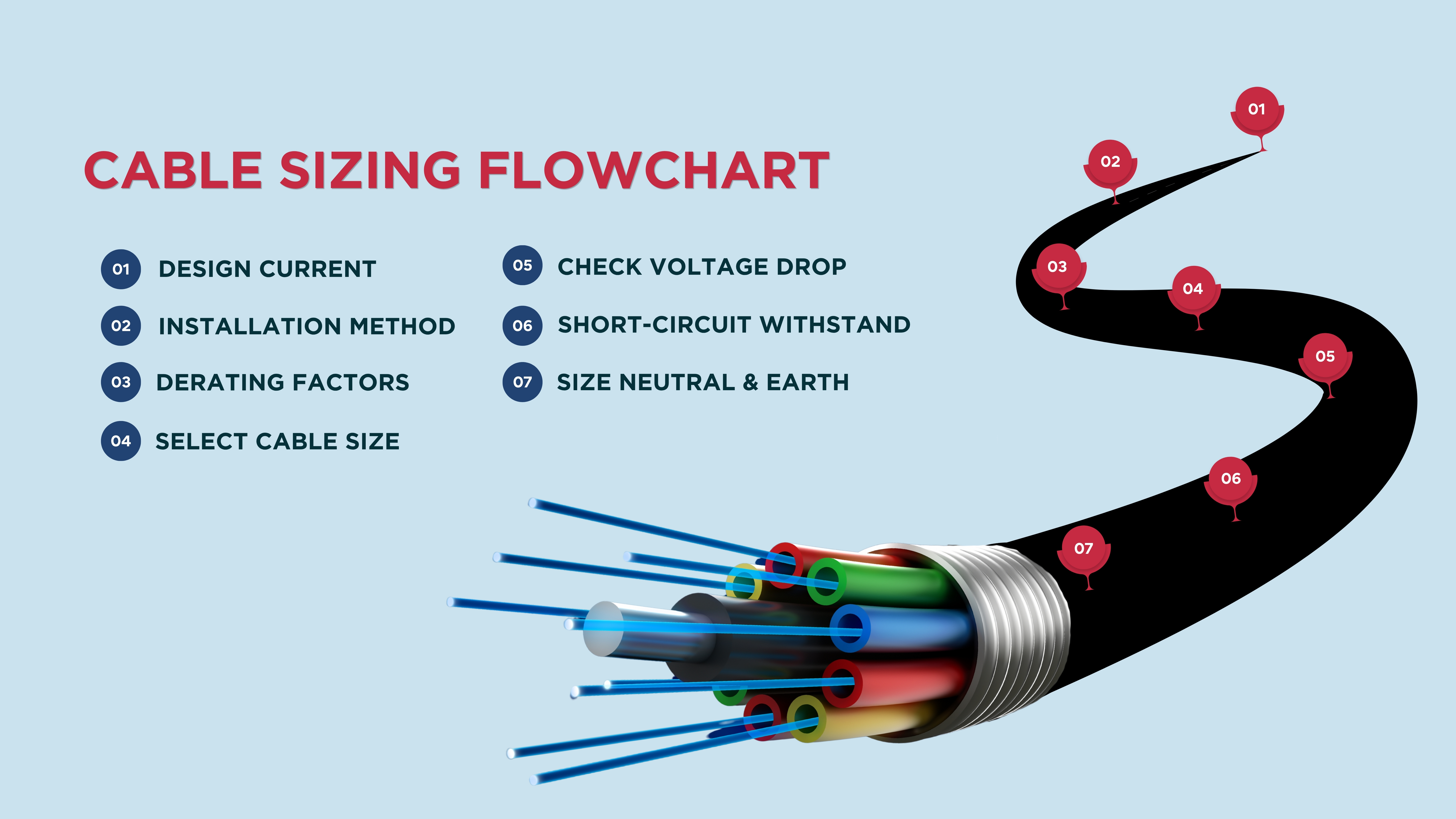
What Are the Steps Involved in Sizing Single Phase Cables?
Step 1: Determine the Design Current (Ib)
The design current is the continuous current the cable is expected to carry under normal operating conditions.
For a single-phase AC load, the formula is: Ib = P ÷ (V × PF).
- P = The load power in watts
- V = Supply voltage (230 V for single-phase in Australia)
- PF = The power factor of the load
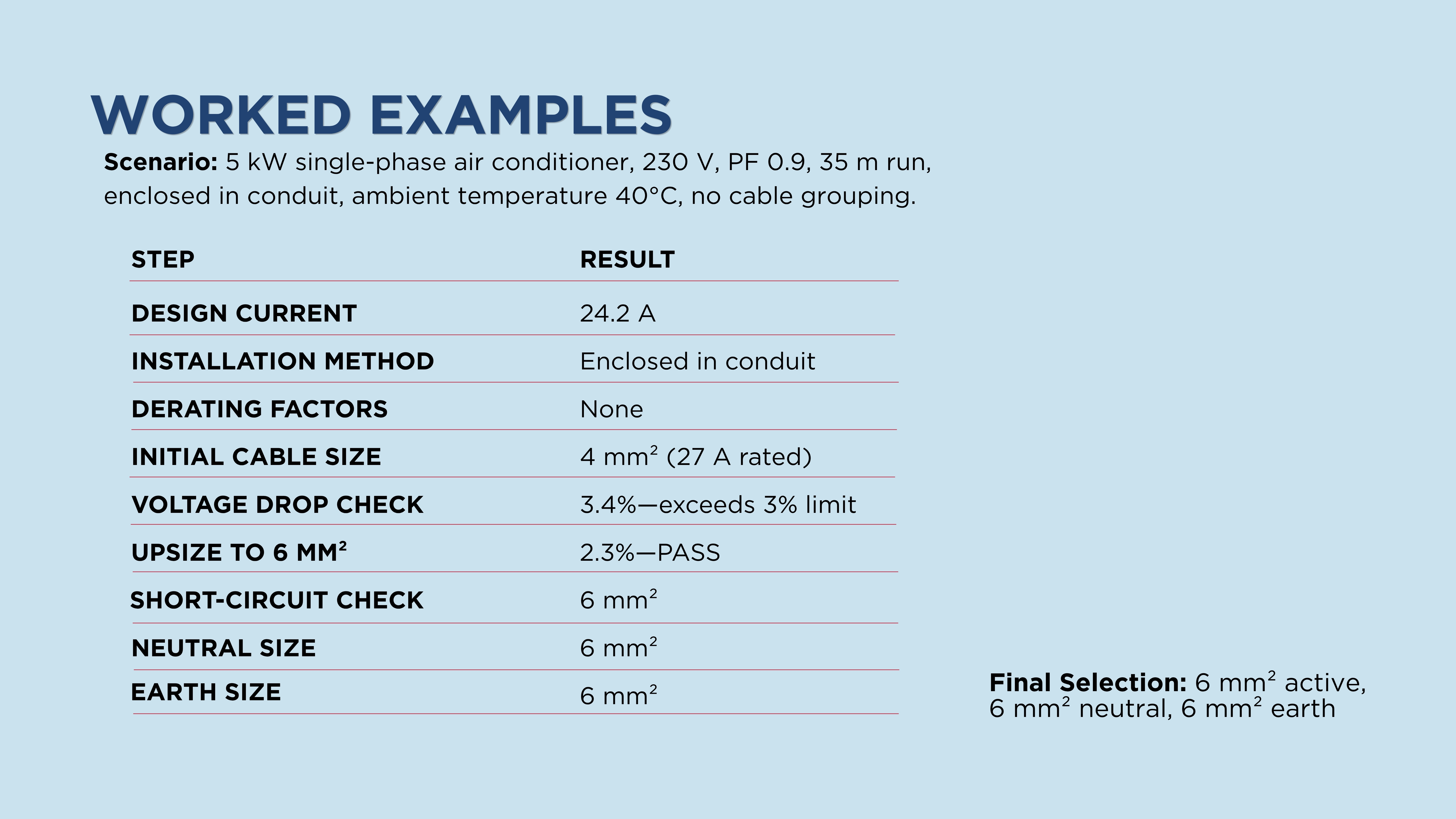
Example: A 5 kW single-phase air conditioning unit with a power factor of 0.9:
Ib = 5,000 ÷ (230 × 0.9) = 24.2 A
For motor loads, multiple by 1.0 to 1.25 to account for starting currents, depending on the motor type and starting method.
Step 2: Identify the Installation Method
The way a cable is installed has a major effect on how effectively heat is dissipated and how much current it can carry. AS/NZS 3008.1.1:2025 defines specific installation methods, each with its own current rating table.
Common single-phase installation methods include:
- Enclosed in conduit (in wall, ceiling, or floor): The most restrictive for heat dissipation
- Clipped direct to surface: Better airflow than enclosed conduit
- Unenclosed in free air: Best thermal performance
- Buried direct in ground: Rating based on soil thermal resistivity and burial depth
- Buried conduit or duct: Slightly reduced rating compared to direct burial
The correct installation method determines which current capacity table from AS/NZS 3008.1.1:2025 you reference. Using the wrong table is one of the most common errors in cable selection.
Step 3: Apply Derating Factors
Standard current ratings in AS/NZS 3008.1.1:2025 assume specific baseline conditions:
- 40°C ambient air temperature for cables in air
- 25°C ground temperature for buried cables
If your installation conditions differ from these baselines, derating factors must be applied to reduce the cable’s effective current-carrying capacity.
The derated current capacity is calculated as: Iz = Ir × (F1 × F2 …)
- Ir = Cable’s base current rating from AS/NZS 3008.1.1:2025
- F1, F2 … = The applicable derating factors
The cable is acceptable when Iz ≥ Ib.
Step 4: Select a Cable Size for Current-Carrying Capacity
Using the derated current capacity requirement (Iz ≥ Ib), refer to the appropriate current rating table in AS/NZS 3008. Then, select the smallest standard cable size whose derated rating meets or exceeds your design current.
Standard cable cross-sectional areas for single-phase copper circuits in Australia are (in mm²): 1.0, 1.5, 2.5, 4, 6, 10, 16, 25, 35, 50, 70, 95, 120, 150, 185, 240, 300.
As a practical reference for copper PVC cables enclosed in conduit at 40°C ambient:
- 2.5 mm² — rated approximately 20 A
- 4 mm² — rated approximately 27 A
- 6 mm² — rated approximately 36 A
- 10 mm² — rated approximately 50 A
- 16 mm² — rated approximately 66 A
These figures vary by installation method and insulation type. Always confirm against the relevant AS/NZS 3008 table for your specific conditions.
Step 5: Check Voltage Drop
Even if a cable passes the current-carrying capacity test, it may fail on voltage drop, particularly for long circuit runs. Voltage drop is calculated using the impedance of the cable.
For a single-phase AC circuit, the voltage drop formula is: Vd = 2 × Ib × L× Zc ÷ 1000.
- Ib = The design current in amps
- L = The one-way cable length in metres
- Zc = The cable impedance in Ω/km
The percentage voltage drop is then: Vd% = (Vd ÷ Vsupply) × 100.
Example: A 24.2 A single-phase load, 35 m cable run, using a 4 mm² copper PVC cable enclosed in conduit. With a resistance of approximately 4.61 Ω/km and negligible reactance at this size:
Vd = 2 × 24.2 × 35 × 4.61 ÷ 1000 = 7.8 V
Vd% = 7.8 ÷ 230 × 100 = 3.4%
This exceeds the recommended 3% sub-circuit limit. Upsize to 6 mm² (resistance ≈ 3.08 Ω/km):
Vd = 2 × 24.2 × 35 × 3.08 ÷ 1000 = 5.2 V → 2.3% ✓
The 6 mm² cable passes both current-carrying capacity and voltage drop checks.
Step 6: Verify Short-Circuit Withstand Capacity
The final check ensures the selected cable can withstand the thermal stress of a fault current during the time taken by the
overcurrent protective device (OCPD) to clear the fault. This is particularly important for cables close to the switchboard where fault levels are highest.
The minimum conductor cross-sectional area for short-circuit withstand is calculated using the adiabatic equation from AS/NZS 3008.1.1:2025 Clause 5: S = (I × √t) ÷ K.
- S = Minimum cross-sectional area in mm²
- I = The prospective short-circuit current in amps
- t = The fault clearing time in seconds
- K = A constant that depends on conductor material and insulation type
If the calculated minimum S is smaller than the cable selected in Steps 4 and 5, the cable passes. If not, upsize accordingly.
Step 7: Size the Neutral and Earth Conductors
Once the active conductor size is confirmed, size the neutral and earth conductors in accordance with AS/NZS 3000:
- Neutral Conductor. For single-phase circuits, the neutral must have the same current-carrying capacity as the active conductor. This means it is the same size as the active under normal conditions.
- Earth Conductor. AS/NZS 3000 Table 5.1 specifies minimum earth sizes based on the active conductor size. For example, a 6 mm² active requires a minimum 6 mm² earth. The earth must also pass a fault current withstand check for phase-to-earth fault conditions.
What Are the Common Single Phase Cable Sizing Mistakes to Avoid?
Common single-phase cable sizing mistakes stem from focusing solely on amperage load while ignoring environmental factors. Key errors include:
- Ignoring Derating Factors. Applying base current ratings without accounting for ambient temperature is a dangerous error in cable selection. Always apply all relevant derating factors before selecting a size.
- Failing to Check Voltage Drop on Long Runs. A circuit that passes the current-carrying capacity check can still fail on voltage drop. This applies to cable runs exceeding 20-30 metres, particularly at smaller cross-sections.
- Using the Wrong Installation Method Table. Applying free-air ratings to a cable that will be enclosed in conduit can result in a cable that overheats. Always match your installation method to the current AS/NZS 3008.1.1:2025 rating table.
- Forgetting the Earth Conductor Check. The protective earth must withstand the phase-to-earth fault current for the duration of fault clearing.
Accurately Size Your Single Phase Cables with CableHero
Effective single phase cable sizing is a precise, multi-step process that goes well beyond a cable that “looks about right” for the load. Every installation must satisfy current-carrying capacity, voltage drop, and short-circuit withstand requirements simultaneously. All should be in compliance with AS/NZS 3008.1.1:2025 and AS/NZS 3000.
By following the seven-step process outlined in this guide, engineers can select the right cable with confidence. This guide can also better assist them in delivering compliant installations and eliminate safety risks that come from undersized wiring.
FAQ
What standard governs single phase cable sizing in Australia?
Cable sizing in Australia is governed by AS/NZS 3008.1.1:2025. It sets out current-carrying capacity tables, derating factors, and voltage drop data for all standard cable types. Cable sizing must also comply with AS/NZS 3000. This specifies the maximum permissible voltage drop and minimum protective earth conductor sizes.
How do I size the protective earth conductor for a single-phase circuit?
Minimum protective earth (PE) conductor sizes for single-phase circuits are specified in AS/NZS 3000 Table 5.1. The earth conductor must also be verified against the short-circuit withstand requirement.
What happens if a cable is undersized for its application?
An undersized cable will operate above its rated conductor temperature under load conditions. This accelerates insulation degradation and increases the risk of insulation breakdown. This will raise fire risks and can cause nuisance tripping of the protective device.

 Standards & Compliance