DC and AC Cable Sizing: A Comprehensive Guide for Your System
Solar panels, battery storage, EV chargers, and the AC distribution networks that power buildings all share one thing: every cable in the system must be correctly sized.
However, here's where engineers and electricians routinely run into trouble.
DC and AC cable sizing are not interchangeable. They share a common methodology, but differ in ways that directly affect which cable you select.
And as of June 19, 2026, those differences are now formalised in Australian law. AS/NZS 3008.1.1:2025 introduces dedicated DC cable tables, eliminating the need to approximate DC values using the 1.155 conversion factor previously applied to AC tables.
Why Are DC and AC Cable Sizing Not the Same?
Before diving into calculations, it's essential to understand why DC circuits cannot simply be sized using AC tables, and what changed with the 2025 standard update.
The Skin Effect: Why DC Resistance Differs
In an AC conductor, current concentrates near the outer surface of the conductor. This is called the skin effect, which increases the effective resistance of the conductor beyond its DC resistance. In a DC conductor, no skin effect occurs.
This skin effect is negligible for:
Smaller cables (up to approximately 25 mm²)
Conductors up to 25 mm²
But for larger conductors (95 mm²+), the DC tables give slightly higher ratings. For large cables in battery, inverter, and utility-scale solar applications, the difference is also material and the correct DC table must be used.
No Reactance in DC Circuits
AC cable voltage drop calculations incorporate both resistance (Rc) and reactance (Xc). DC circuits have no reactance. The voltage drop formula for a DC circuit therefore uses resistance only, which simplifies the calculation but changes which values you extract from the standard.
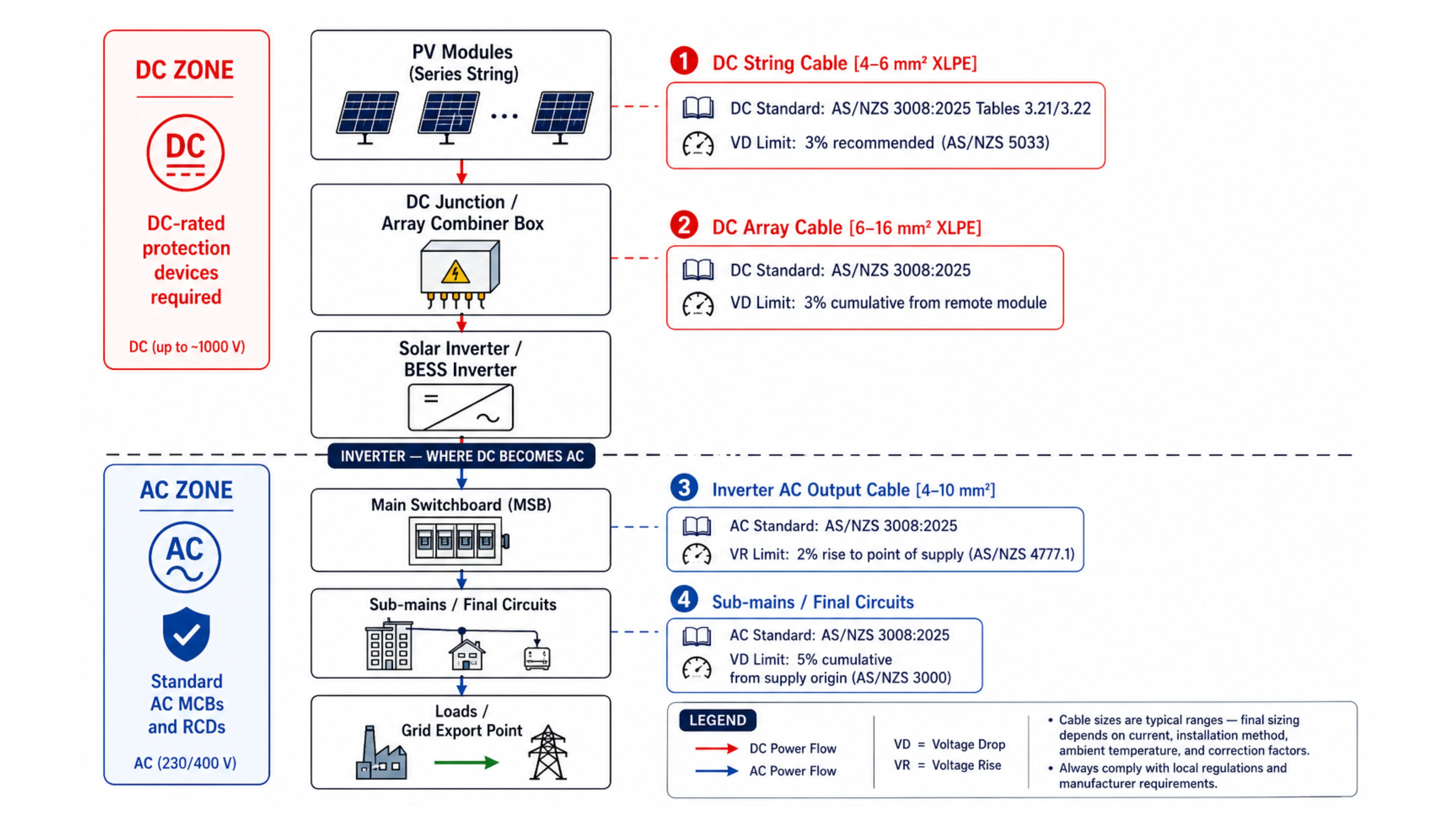
Different Voltage Drop Limits
AC and DC circuits operate under different voltage drop limits in Australia. The applicable limits depend on the standard and circuit type.
5%: Standard LV installation connected to distributed network
7%: Installation supplied from a dedicated substation
2%: Inverter AC circuit to point of supply (AS/NZS 4777.1:2024, where no high-export-voltage protection is provided)
DC circuits (application-standard dependent):
3% recommended / 5% maximum: Solar PV DC string cables from most remote module to inverter input (AS/NZS 5033:2021 Clause 4.4.2.4)
3%: Battery DC cables (design guideline)
Under AS/NZS 5033:2021, a recommended 3% voltage drop is permitted on the DC side between the PV array or DC battery and the inverter. On the AC side between the point of attachment to the grid and the Inverter, a 2% voltage rise limit is permitted.
Arc Fault Behaviour
DC arcs are harder to extinguish than AC arcs because there is no natural current zero crossing. DC-rated circuit breakers and fuses must be used, and cable fault current withstand calculations should account for longer clearing times.
This affects both protection device selection and cable short-circuit withstand calculations. A cable sized using AC short-circuit parameters may not be adequate in a DC circuit where the protective device takes longer to clear. C8.2.webp494.15 KB
How Are DC and AC Cables Sized?
Both DC and AC cable sizing follow the same four-step methodology under AS/NZS 3008.1.1:2025. The inputs and formulas at each step differ, but the sequence is identical.
Step 1: Determine the Design Current
AC Single-Phase: Ib = P ÷ (V × PF)
AC Three-Phase: Ib = P ÷ (√3 × VL-L × PF)
DC (Solar PV String): Ib = 1.25 × Isc
DC (Battery/Inverter): Ib = Maximum continuous DC current draw of the inverter or battery output
The 1.25 × Isc multiplier for solar PV string cables accounts for the reverse current that can flow through a faulted string—a DC-specific protection consideration that has no AC equivalent.
Step 2: Select the Correct AS/NZS 3008 Table
The 2025 standard simplifies DC sizing by introducing dedicated tables. DC cable current-carrying capacity values are now found in Tables 3.21 and 3.22, replacing the previous workaround of adapting AC tables.
For AC circuits, the correct table depends on:
Cable Type: Multicore or Single-Core
Conductor Material: Copper or Aluminium
Insulation Type: PVC (V-90) or XLPE (X-90)
Installation Method: In Conduit, Clipped Direct, Free Air, Buried Direct, In Buried Conduit
For DC circuits from June 2026:
Tables 3.21 and 3.22 for DC current-carrying capacity
Table 4.16 for DC voltage drop values
Solar PV DC string circuits and EV charging infrastructure now have their own table sets rather than being approximated from general-purpose installation methods.
Step 3: Apply Correction Factors
Both AC and DC cables use the same correction factor framework from AS/NZS 3008.1.1:2025. The 2025 edition derating tables apply equally to DC circuits.
The key correction factors are:
Temperature Correction: Reference conditions: 40°C ambient for in-air cables; 25°C for buried cables. For DC solar string cables on rooftops, ambient temperature routinely exceeds 60–70°C in Australian summers.
Grouping Correction: When multiple DC string cables share a conduit or cable tray, the grouping correction factor must be applied. On large solar farms where dozens of string cables may share a single conduit run, this can reduce the cable rating by 30–40%.
Solar Radiation Correction: The solar radiation guidance has been clarified with a more explicit methodology, aligning with IEC 60364-5-52 Amendment 1.
Derated current capacity: Iz = Ir × CF_temp × CF_group × CF_sunlight.
Cable is acceptable when: Iz ≥ Ib.
Step 4: Voltage Drop Calculation
This is where DC and AC cable sizing diverge most significantly.
AC single-phase voltage drop: Vd = 2 × I × L × (Rc·cosφ + Xc·sinφ) ÷ 1000
AC three-phase voltage drop: Vd = √3 × I × L × (Rc·cosφ + Xc·sinφ) ÷ 1000
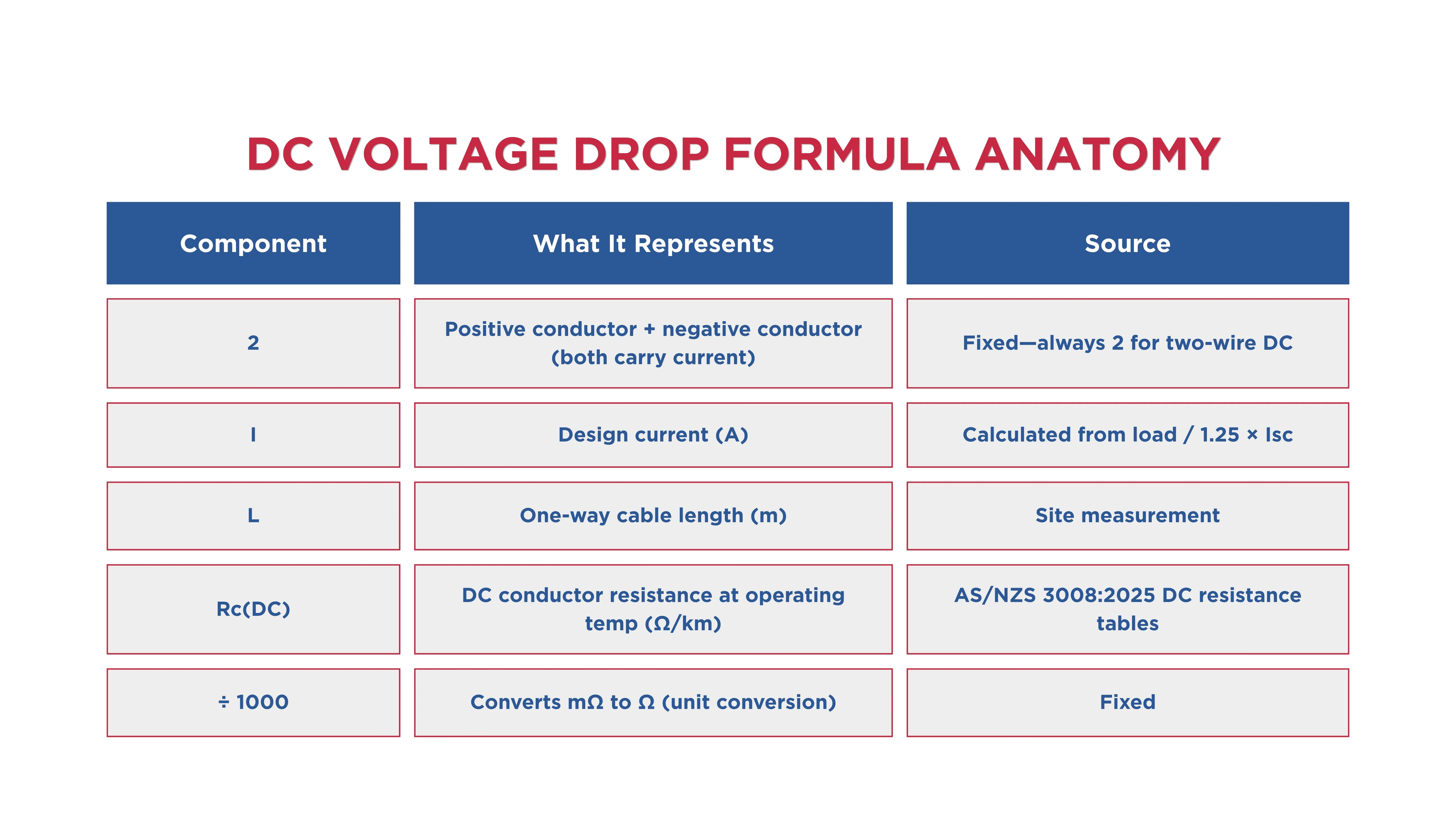
The DC formula has no reactance term (Xc = 0 for DC) and no power factor term (DC circuits are unity power factor by definition).
The factor of 2 accounts for both the positive and negative conductors. DC resistance values (Rc) come from the new DC resistance tables in AS/NZS 3008.1.1:2025.
Worked Examples
DC Solar String Cable
Scenario: Solar PV string, Isc = 12 A, Vmp = 40 V per module, 10 modules in series (Vstring = 400 V), cable length 35 m, XLPE insulation, two-core DC cable, installed in conduit, ambient 60°C.
Step 1 — Design current: Ib = 1.25 × 12 = 15 A
Step 2 — Table selection: AS/NZS 3008.1.1:2025 Table 3.21: DC, two-core, XLPE, in conduit; Base rating for 4 mm²: approximately 30 A
Step 3 — Correction factors: Temperature correction at 60°C for XLPE: ≈ 0.71; No grouping (single cable in conduit): 1.00
Iz = 30 × 0.71 = 21.3 A ≥ 15 A ✓
Step 4 — Voltage drop: Rc(DC) for 4 mm² copper ≈ 4.95 Ω/km (from AS/NZS 3008:2025 DC table)
Vd = 2 × 15 × 35 × 4.95 ÷ 1000 = 5.2 V
Percentage: 5.2 ÷ 400 × 100 = 1.3% ✓ → Within the 3% recommended limit
Result: 4 mm² XLPE DC cable → PASS on both CCC and voltage drop AC Inverter Output Cable (Single-Phase)
Scenario: Single-phase inverter, 5 kW output, 230 V, PF 0.99 (typical for modern inverter), cable length 8 m from inverter to MSB, XLPE, multicore, clipped to surface, 40°C ambient.
Step 2 — Table selection: AC, multicore XLPE, clipped direct—base rating for 4 mm²: approximately 40 A
Step 3 — Correction factors: Temperature: 40°C (no derating needed)
Iz = 40 A ≥ 22 A ✓
Step 4 — Voltage drop: For 4 mm² XLPE (Rc ≈ 4.61 Ω/km, Xc negligible at this size)
Vd = 2 × 22 × 8 × 4.61 ÷ 1000 = 1.62 V
But the applicable limit for this AC inverter circuit is 2% rise (AS/NZS 4777.1) = 4.6 V max.
1.62 V = 0.7% ✓ Check also: AS/NZS 3000 for voltage drop from point of supply: 0.7% (this section only—cumulative must be ≤ 5% from supply origin).
Result: 4 mm² multicore XLPE → PASS
What Changed for DC Cable Sizing Under the 2025 Standard Update?
The transition to the 2025 standard marks a step forward in aligning cable selection with the high-voltage capabilities now permitted in residential systems (the '1000V rule' introduced in AS/NZS 4777.1:2024). C8.3.webp411.65 KB
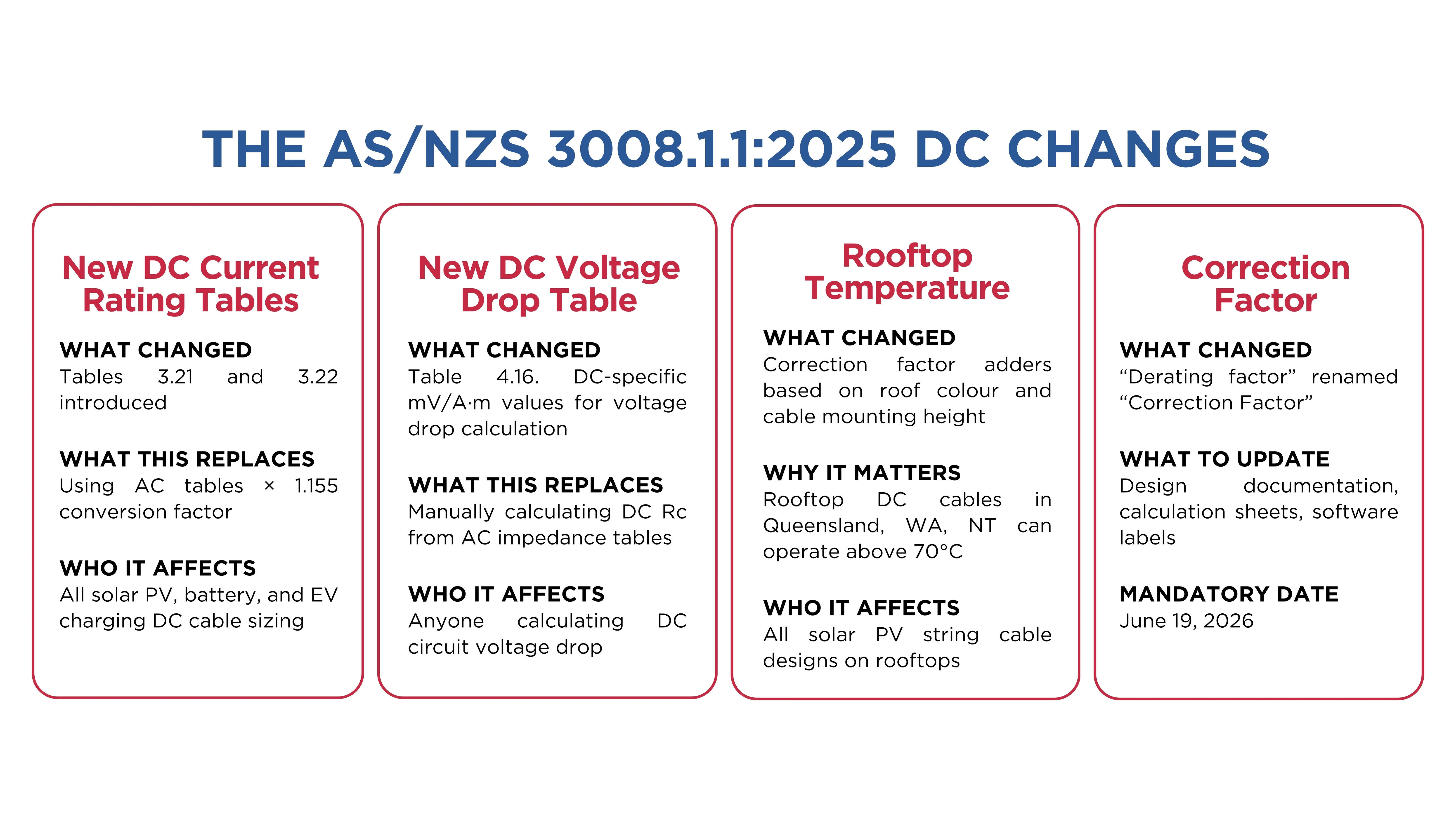
The four most significant changes affecting DC cable sizing in practice are:
New dedicated DC current rating tables (Table 3.21 and 3.22). The old method of using AC tables with a 1.155 correction factor is no longer compliant after June 19, 2026. While the numerical results are similar for smaller cables, the dedicated tables are the authoritative reference going forward.
New DC voltage drop table (Table 4.16). Voltage drop for DC is now found in Table 4.16. The table provides mV/A·m values for DC circuits directly—no calculation from AC impedance tables required.
Solar radiation correction factors–updated methodology. The recommended temperature adder for cables in direct sunlight has been refined from a general 'approximately 15°C' to specific values based on cable colour and geographic location.
Terminology: “Derating factor” is now “Correction factor.” The industry-standard term "derating factor" has been officially replaced with Correction Factor (CF). This change aligns the standard with other international benchmarks and modern electrical terminology.
From June 19, 2026, all new DC cable sizing in Australia must comply with AS/NZS 3008.1.1:2025. Designs still referencing the 2017 edition or using the 1.155 AC-to-DC conversion workaround are non-compliant.
Size DC and AC Cables Accurately With CableHero
Manual DC and AC cable sizing takes time and creates compliance risk. One wrong table, one missed correction factor, or one AC formula applied to a DC circuit, and the result is non-compliant.
CableHero is Australia's purpose-built cable sizing platform, built specifically for AS/NZS 3008.1.1:2025 and AS/NZS 3000 compliance, covering both DC and AC cable sizing.
With CableHero, you can:
Size DC cables using the correct 2025 DC current rating tables and DC voltage drop formula—no AC-to-DC conversion workarounds
Size AC cables for single-phase and three-phase circuits with automatic correction factor application, cumulative voltage drop tracking, and short-circuit withstand verification
Check voltage rise for solar PV inverter AC circuits against the AS/NZS 4777.1 2% limit
Apply all correction factors automatically, including the updated rooftop temperature adders from AS/NZS 3008:2025 for solar DC string cables
Generate branded PDF compliance reports for both DC and AC circuits, ready for CER, DNSP, or inspection authority submission
Whether you're sizing solar PV string cables, battery-to-inverter DC cables, inverter AC output circuits, or commercial sub-mains, CableHero gives you the correct result under the correct 2025 standard every time.
Use CableHero today to size your AC and DC cables accurately. No credit card required.
FAQ
What is the difference between DC and AC cable sizing in Australia?
DC and AC cable sizing follow the same four-step methodology but differ in key ways. For DC circuits, the design current for solar PV strings uses 1.25 × Isc (to account for reverse current), the voltage drop formula has no reactance term (no Xc·sinφ component), and the voltage drop limit is 3% recommended (versus 5% for standard AC circuits).
What voltage drop limit applies to DC solar PV cables in Australia?
Under AS/NZS 5033:2021, a recommended 3% voltage drop is permitted on the DC side between the PV array or DC battery and the inverter. The maximum permitted is 5% of Vmp per AS/NZS 5033:2021 Clause 4.4.2.4 for PV arrays operating above 120 V. For battery DC cables, 3% is the standard design target. The DC voltage drop limit is tighter than the standard 5% AC limit under AS/NZS 3000, and it compounds over the system's operational life.
Do I still need to use the 1.155 correction factor for DC cable sizing after the AS/NZS 3008.1.1:2025 update?
No. The 2025 standard simplifies DC sizing by introducing dedicated tables: DC cable current-carrying capacity values are now found in Tables 3.21 and 3.22, replacing the previous workaround of adapting AC tables.

 Cable Sizing
 Cable Sizing
 Cable Sizing