Voltage drop is one of the most common reasons electrical installations fail compliance checks in Australia. It's also one of the most misunderstood.
AS NZS 3000 sets clear limits on how much voltage can be lost between the point of supply and any piece of connected equipment.
This guide covers everything you need to know about applying AS NZS 3000 for voltage drop: what the standard actually requires, how to calculate it correctly, and the mistakes that consistently trip up even experienced designers.
What Is AS NZS 3000 and Why Does It Cover Voltage Drop?
AS/NZS 3000:2018, formally titled Electrical Installations, is the foundational standard governing the design, construction, and verification of low-voltage electrical installations across Australia and New Zealand. Its core objectives are to:
- Minimise the risk of electric shock, fire, and injury
- Promote consistent design and installation practices across jurisdictions
- Ensure electrical systems operate safely, efficiently, and reliably
In Australia, the standard is referenced directly in state and territory electrical safety regulations, making it legally enforceable.
Voltage drop sits squarely within that scope.
When excessive voltage drop occurs, equipment receives less voltage than it was designed to operate on. The result is reduced performance, premature failure, overheating, and in some cases, a genuine safety risk.
What Does AS NZS 3000 Say About Voltage Drop?
Section 3.6 of AS/NZS 3000:2018 is the governing clause for voltage drop in low-voltage installations. It establishes a clear principle: the voltage drop from the point of supply to any point in the installation must not impair the proper functioning of any equipment connected to it.
The standard sets a maximum voltage drop of 5% of the nominal supply voltage, measured from the origin of the installation to the terminals of any electrical appliance.
“Origin of the Installation”
The origin is typically the main switchboard where the supply authority's metering is located. It’s not the transformer or street network, which is an important distinction. The 5% budget starts at your main switchboard and must cover every cable run downstream from that point.
The Voltage Drop Budget in Real Numbers
For Australian installations operating at nominal voltages:
Consumer Mains: The 2% Sub-Limit
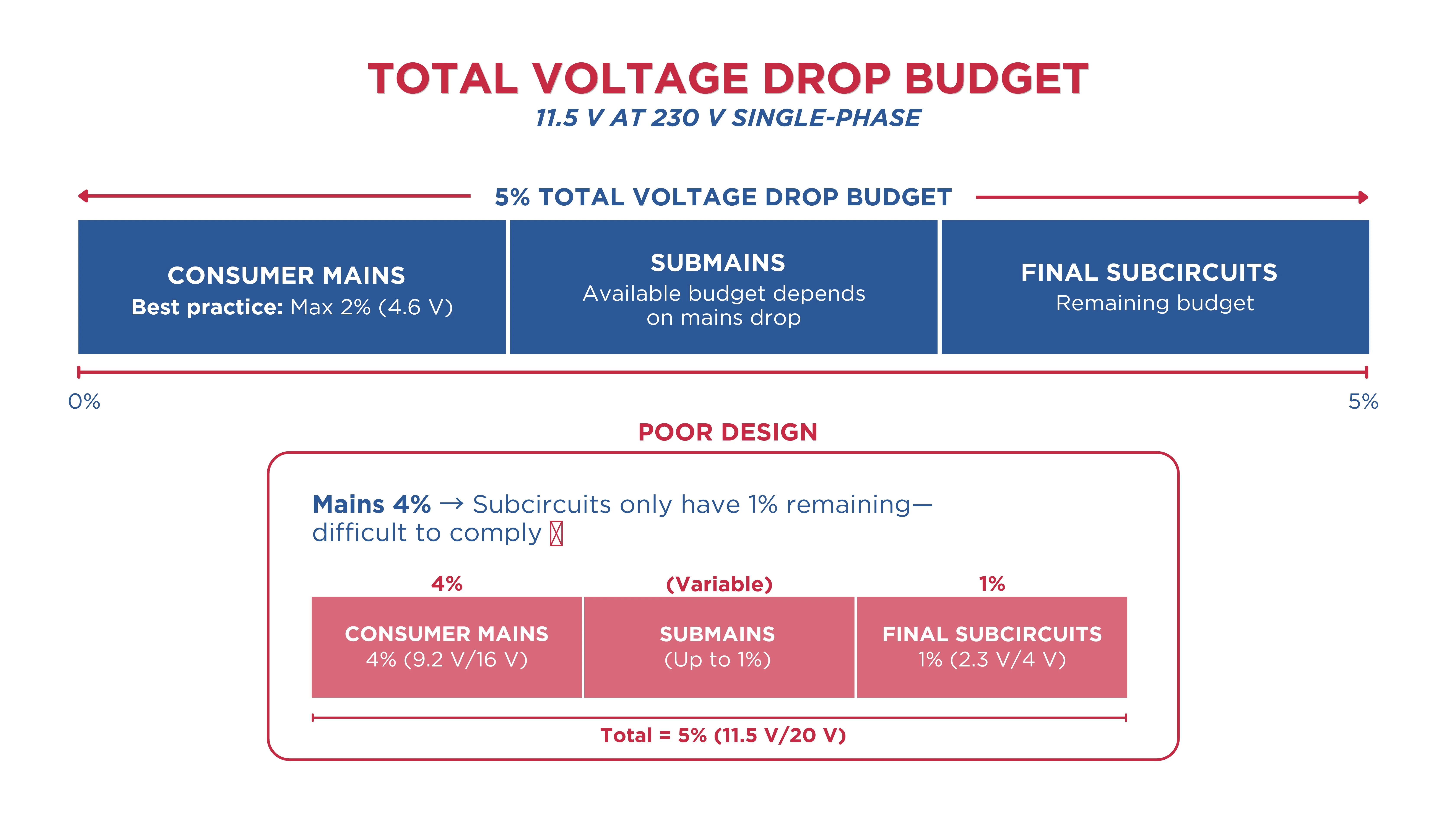
For the consumer mains, best practice is to limit voltage drop to 2%. This leaves the remaining budget for submains and final subcircuits downstream.
This allocation matters more than most designers realise. If your consumer mains consume 3–4% of the 5% budget, every subcircuit downstream is constrained to less than 2%, which can force significant cable upsizing on longer runs.
The Total Budget Must Be Shared Across All Segments
This is the most common source of non-compliance. The 5% limit is a cumulative total, not a limit per circuit segment. Every volt lost in the consumer mains, submains, and final subcircuits is subtracted from the same budget.
For example, on a 230 V single-phase installation:
- Consumer mains voltage drop: 6 V (2.6%)
- Remaining budget for submains and final subcircuits: 5.5 V (2.4%)
Design without tracking this cumulative total and you will overshoot the limit, often without realising it until the installation is already wired.
Where Do the Voltage Drop Requirements Apply?
AS NZS 3000 for voltage drop applies to all parts of a low-voltage electrical installation, including:
- Consumer Mains. From the point of supply to the main switchboard.
- Submains. From the main switchboard to distribution boards or sub-switchboards. These can carry significant current across long distances in commercial and industrial buildings, making them a common source of excessive drop.
- Final Subcircuits. From the distribution board to individual outlets, fixtures, and fixed equipment. These are the circuits most frequently flagged during compliance checks, particularly on long runs in warehouses, rural properties, and large commercial floors.
- Special Circuits. AS/NZS 3000 Clause 3.6.3 recommends limiting voltage drop to 3% for lighting circuits to avoid perceptible dimming.
How Is Voltage Drop Calculated Under AS NZS 3000?
AS NZS 3000 for voltage drop works in conjunction with AS/NZS 3008.1.1, which provides the cable impedance values needed to perform accurate calculations.
There are three approaches, varying in complexity and accuracy
Method 1: Ohm’s Law (Basic Estimation)
The simplest approach applies the fundamental relationship:
VD = I × R
- I = Current in Amperes (A)
- R = Total Circuit Resistance in Ohms (Ω)
This method is useful for quick checks and simple, purely resistive circuits. It does not account for cable reactance or power factor, so it can underestimate voltage drop in circuits with inductive loads or large conductors.
Method 2: The mV/A/m Formula (Standard Practice)
This is the method most commonly used in Australian electrical design and is directly supported by the tables in AS/NZS 3008:
Single-Phase: VD = (I × L × 2 × mV/A/m) / 1000
Three-Phase: VD = (I × L × √3 × mV/A/m) / 1000
- I = Design Current in Amperes
- L= One-way Circuit Length in Metres
- mV/A/m = Millivolts per ampere per metre, from AS/NZS 3008 impedance tables
- The factor of 2 in single-phase accounts for the go-and-return current path
- √3 (approximately 1.732) is used for balanced three-phase circuits
For example, on a 230 V single-phase installation:
- Circuit current: 20 A
- Cable run: 45 m
- 4 mm² copper, mV/A/m ≈ 11.2 mV/A/m
VD = (20 × 45 × 2 × 11.2) / 1000 = 20.2 V = 8.8% — exceeds the 5% limit. Upsize to 6 mm².
Method 3: Power Factor Method (Most Accurate)
For commercial and industrial circuits, the power factor method gives the most accurate result:
Single-Phase: VD = 2 × I × L × (R·cosφ + X·sinφ) / 1000
Three-Phase: VD = √3 × I × L × (R·cosφ + X·sinφ) / 1000
- R = Conductor resistance per metre (Ω/m), from AS/NZS 3008 tables
- X = Conductor reactance per metre (Ω/m), from AS/NZS 3008 tables
- cosφ = Power factor of the load
- sinφ = Reactive component (√(1 − cos²φ))
This method matters most for large conductors. For cables above approximately 50 mm², reactance becomes a significant contributor to
voltage drop. Ignoring it can lead to a result that is substantially lower than reality.
What Key Factors Affect Voltage Drop?
Understanding what drives voltage drop helps you make smarter design decisions, when you're trying to bring a circuit back within limits without simply upsizing the cable.
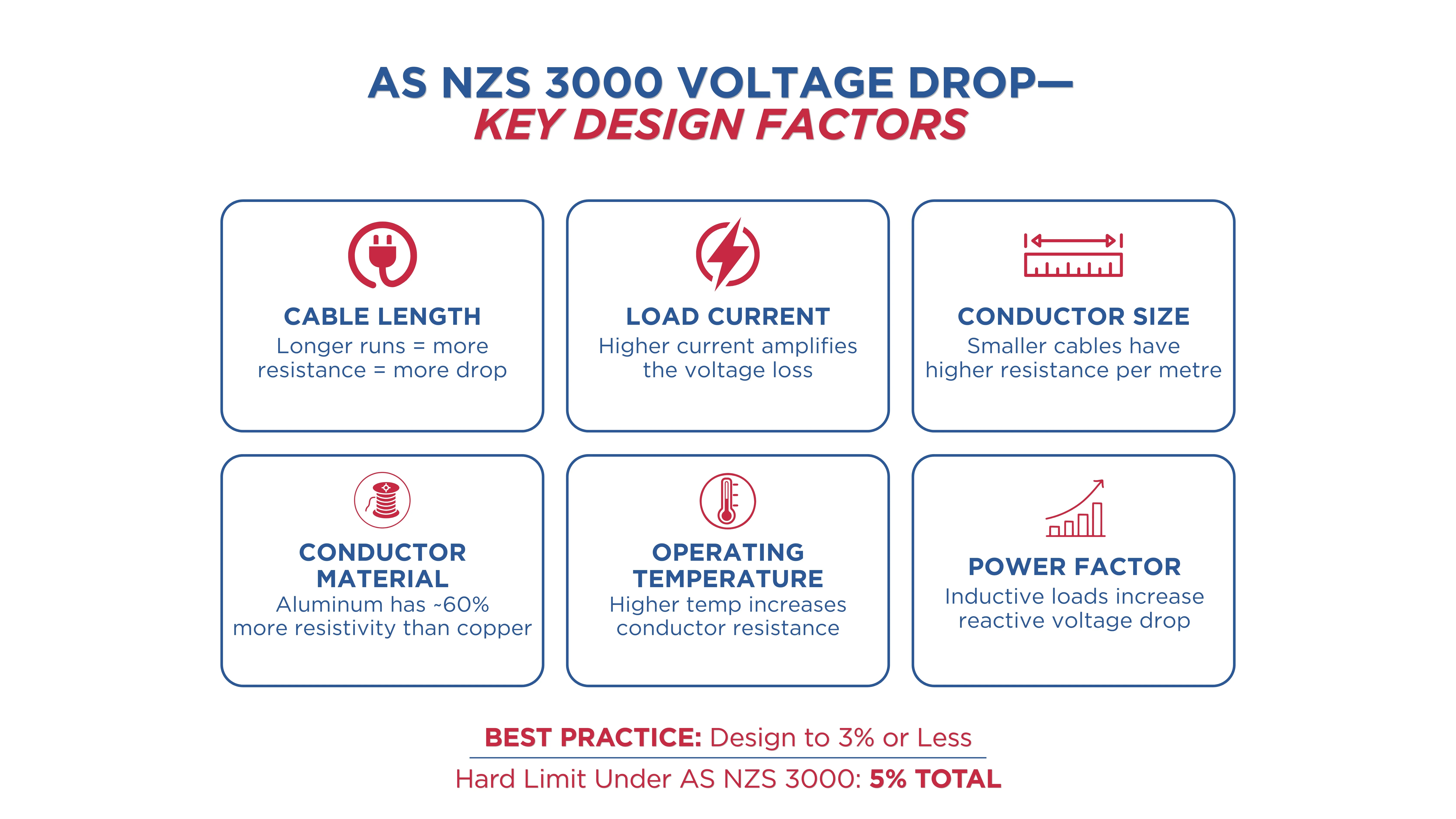
- Cable Length. Voltage drop increases linearly with length. Doubling the circuit length doubles the drop. This is the primary driver on rural, warehouse, and large-format commercial installations.
- Load Current. Higher current means more drop. Voltage drop is directly proportional to current, so circuits close to their rated capacity will show maximum drop.
- Conductor Cross-Sectional Area. Larger cables have lower resistance per metre. Moving from 2.5 mm² to 4 mm² reduces resistance by approximately 37%, directly reducing voltage drop.
- Conductor Material. Copper has approximately 60% of the resistivity of aluminium, making it the preferred choice for smaller conductors. Aluminium is typically only used in Australian installations at 16 mm² and above.
- Operating Temperature. Cable resistance increases with temperature. The mV/A/m values in AS/NZS 3008 are referenced at the conductor's rated operating temperature, so this is already accounted for when you use the standard tables.
- Power Factor. For inductive loads, a lower power factor increases the reactive component of voltage drop, particularly in larger cables with significant reactance.
How Is Voltage Drop Reduced?
When a circuit calculation exceeds the 5% limit, these are your options:
- Upsize the Conductor. Moving to the next standard cable size is the most common fix. It directly reduces resistance per metre and requires no changes to the circuit layout.
- Shorten the Cable Run. Relocating the distribution board or sub-switchboard closer to the load reduces circuit length.
- Use Copper Rather than Aluminium. If an aluminium submain is exceeding the voltage drop limit, switching to copper of the same cross-section reduces drop by approximately 40%.
- Split the Load Across Multiple Circuits. Distributing the load between two circuits reduces the current on each. This proportionally reduces voltage drop on both.
- Use Parallel Cables. Two smaller cables in parallel can achieve the same or lower combined resistance as a single larger cable, sometimes at a lower installed cost.
- Manage the Voltage Drop Budget Across Segments. If the consumer mains and submains are consuming most of the 5% budget, review whether those upstream cables can be upsized.
What Are the Common Compliance Mistakes with AS NZS 3000 Voltage Drop?
These are the errors that show up repeatedly during inspections and compliance checks:
- Treating 5% as the limit for each circuit segment. The 5% applies from the point of supply to the furthest point of utilisation. Each segment eats into the same budget.
- Ignoring cable reactance on large conductors. For conductors at 50 mm² and above, omitting the reactance term in voltage drop calculations can produce significantly underestimated results.
- Using Ohm’s Law for inductive circuits. The simple V = IR formula is not accurate enough for motor or industrial circuits. The power factor method is required.
- Failing to account for temperature. Always use the mV/A/m values that correspond to the cable's rated operating temperature.
- Designing to exactly 5%. Any variation in actual conditions will push you over the limit. Best practice is to design to 3% or less where possible, with 5% as the hard ceiling.
- Not documenting the calculation. AS/NZS 3000 compliance requires that the design be verifiable.
Size Cables Confidently with CableHero
Voltage drop calculations don't have to be a spreadsheet exercise. CableHero is professional cable sizing software built specifically for Australian electricians and engineers, fully aligned with AS/NZS 3000:2018 and AS/NZS 3008.1.1.2025.
With CableHero, you can:
- Calculate voltage drop for single-phase and three-phase circuits instantly, using accurate mV/A/m values from AS/NZS 3008
- Track cumulative voltage drop across consumer mains, submains, and final subcircuits
- Apply power factor corrections automatically for inductive loads
- Generate compliant PDF reports, ready for certification and DNSP submission
Whether you're designing a residential fit-out or a multi-level commercial installation, CableHero does the heavy lifting.
Try CableHero free today. No credit card required.
FAQ
What is the maximum voltage drop allowed under AS NZS 3000?
The maximum voltage drop under AS/NZS 3000:2018 Clause 3.6 is 5% of the nominal supply voltage. This is measured from the point of supply to the furthest point of utilisation.
Does the 5% voltage drop limit apply to each circuit or to the whole installation?
It applies to the whole installation and not each segment independently. The 5% is a cumulative budget shared across consumer mains, submains, and final subcircuits. A common approach is to limit consumer mains to 2%, which leaves 3% for the subcircuits downstream.
What is the difference between the AS NZS 3000 voltage drop limit and the AS NZS 3008 calculation method?
AS NZS 3000 sets the compliance limit. AS/NZS 3008.1.1 provides the calculation method and data. You need both standards to complete a compliant voltage drop calculation: 3000 tells you the limit, 3008 gives you the numbers to calculate against it.


 Cable Sizing