How to Read and Interpret a Cable Schedule Like a Pro
27Jul
Ahmed Tayeh
Cable Sizing
How to Read and Interpret a Cable Schedule Like a Pro
If you've ever stood in a distribution board or switchroom trying to trace an unlabelled cable back to its source, you understand exactly why a cable schedule matters. A cable schedule is the single document that answers every practical question about every cable on a project:
Where does it come from
Where is it going
What type and size is it
How long is it
What is it protected by
What standard does it comply with
Done well, a cable schedule is one of the most useful documents in a project's technical record. Done poorly, it creates the exact tracing and troubleshooting problems that cost time and money throughout construction, commissioning, and the entire operational life of the installation.
This guide explains what every column means, how to cross-reference a cable schedule against related drawings, how to verify one for accuracy, and how to produce one efficiently for Australian electrical projects.
What Is an Electrical Cable Schedule?
A cable schedule is a table of information about cables for a particular installation. This can relate to cables for power, lighting, communication, security, fire, etc. A building floor plan would often be associated with the cable schedule and the type of information shown could include cable type, size, and route.
The scope of a cable schedule depends on the project type:
On commercial and industrial electrical projects: The cable schedule covers all power, lighting, and control cables.
On EPC energy projects: The cable schedule acts as a master reference throughout the engineering, procurement, construction, commissioning, and maintenance phases.
On instrumentation and process control projects: The cable schedule crosses into signal cables, HART loops, Modbus communication cables, and fire and gas detection system wiring.
What Are the Standard Columns in an Electrical Cable Schedule?
The exact columns vary between organisations and project types, but every well-structured cable schedule contains the following core fields.
Column 1: Cable Number (Cable Tag)
The cable number is the unique identifier for each cable in the installation. Every cable gets one, and it is used consistently across the cable schedule, the single-line diagram, the wiring diagrams, the loop drawings, and the as-built records.
Assign unique cable numbers using a structured numbering scheme that typically encodes the project, area, cable type, and sequence. For example:
SR-EL-PWR-0042 identifies cable 42 in the electrical power category of the Sunridge project.
The cable number is the cross-reference key that links every other drawing and document to this specific cable. When a construction supervisor queries which cable connects motor MCC-07 to pump P-12, the cable number is what the cable schedule is searched by.
Column 2: Cable Description
A plain-language description of what the cable serves.
Power cables: Supply to pump P-12 from MCC-07
Control cables: Start/stop and feedback signals, motor control centre to local control panel
Instrumentation: 4–20 mA signal, flow transmitter FT-01 to DCS cabinet
This column is used by installation electricians, commissioning engineers, and maintenance technicians to understand the cable's function without needing to trace the wiring diagram. It is also the first check a document controller performs when verifying that a cable has been correctly assigned to its service.
Column 3: From Location and Tag
Typically recorded as both a location (e.g., "Main Switchboard MSB-01, DB01") and a specific terminal or terminal block reference. From/To equipment tags must match:
Instrument Index
Electrical Load List/SLDs
JB schedules
Telecom Index
Errors in the From field are among the most common cable schedule mistakes, particularly when the schedule is prepared before the single-line diagram is finalised, and terminal references are populated later but inconsistently.
Column 4: To Location and Tag
The destination of the cable, where it terminates at the load end.
For a motor feeder: the motor terminal box
For a lighting circuit: the first fitting or the local isolator
For an instrumentation cable: the instrument connection head or local junction box
Together, the From and To fields define the cable's routing origin and destination. They are used by the construction team to confirm the cable path before pulling, and by the commissioning team to verify loop integrity during testing.
Column 5: Cable Type and Specification
The cable type column specifies the electrical and physical specification of the cable. For Australian power projects this typically includes:
Insulation Material: PVC (V-90) or XLPE (X-90 / X-HF), defines the thermal rating and fire performance
Sheathing: PVC outer sheath, or LSZH (Low Smoke Zero Halogen) for fire-rated areas
Armouring: SWA (Steel Wire Armoured) or AWA (Aluminium Wire Armoured) for mechanical protection in buried or exposed cable tray applications; unarmoured for cables in conduit
Voltage Rating: 0.6/1 kV for standard LV power cables; 3.3 kV, 6.6 kV, or 11 kV for MV cables in substations and utility-scale projects
Fire Rating: Fire-resistant (FLP, MICC, FP200) for essential services cables required to maintain circuit integrity under fire conditions
Column 6: Number of Cores and Size
The conductor configuration—how many cores and what cross-sectional area.
For power cables: 3-core (three-phase without neutral), 4-core (three-phase with neutral), or 2-core (single-phase) in the appropriate mm² size derived from the cable sizing calculation
For instrumentation cables: Pairs (2 conductors twisted together), triads (3 conductors), or multi-pair configurations, with individual conductor size typically 0.5 mm² to 1.5 mm² for signal circuits
This column is the output of the cable sizing calculation. The core count and conductor size that satisfies current-carrying capacity, voltage drop, and short-circuit withstand requirements under AS/NZS 3008.1.1. It must be consistent with the cable sizing calculation documentation and the single-line diagram.
Column 7: Installation Method and Route
The physical path the cable takes, which cable trays, conduit runs, trenches, or duct banks it travels through, and what installation method applies at each section of the route.
The installation method directly affects cable sizing. A cable running free in air has a higher current-carrying capacity than the same cable enclosed in a conduit, and the cable schedule must reflect the installation method applied in the cable sizing calculation.
For long cable runs on large projects, the route column may reference a separate cable route drawing or cable tray layout rather than spelling out every tray section. On solar farm projects, the DC string cable routes from module strings to inverter pads are typically shown on a reticulation layout drawing that the cable schedule references.
Column 8: Cable Length
Cable length is calculated from the plot plan or cable tray routing drawings as the sum of horizontal tray runs, vertical drops, equipment termination slack (typically 2 m per end), and a 10% project spare.
Cable schedule will be referred during the construction phase; however, it is not recommended to cut the cable based on the length information stated on the cable schedule. The cable schedule length is an estimate used for material procurement.
The 10% spare included in procurement lengths accounts for unexpected routing changes, additional vertical drops, and the contingency needed when cable tray routing drawings don't perfectly reflect as-built site conditions.
Column 9: Voltage Drop and Sizing Compliance
For larger projects and utility-scale installations, the cable schedule includes a voltage drop column. This is the calculated percentage voltage drop for the cable run, confirming it is within the AS/NZS 3000 limit of 5%.
This column is populated from the cable sizing calculation and provides an immediately accessible compliance reference. The project engineer reviewing the cable schedule can verify at a glance that every cable meets its voltage drop requirement without reviewing individual calculation sheets.
Column 10: Circuit Breaker/Fuse Reference
The protective device that protects the cable. This column is used during commissioning to confirm protection coordination, and during operations and maintenance to identify which protective device must be isolated before work can be performed on a specific cable.
Terminal numbers and polarity/signal naming must be consistent with interconnection/loop drawings. For control and instrumentation cables, this column also captures the specific terminal numbers at each end, enabling commissioning engineers to perform loop checks without separately consulting the wiring diagrams.
Column 11: Remarks and Status
A freeform notes column used to record any special installation requirements, deviation from the standard specification, installation hold points, commissioning test status, or as-built modifications.
The status column tracks the cable through the construction lifecycle: not installed → cable pulled → terminated → tested → commissioned. On large projects, this column is updated by the site construction team and forms part of the project's quality record. C10.2.webp300.88 KB
How Is a Cable Schedule Cross-Referenced with Other Project Documents?
A cable schedule does not stand alone. It is one document in an interconnected set of project deliverables, and its value depends on consistency with every other document it references.
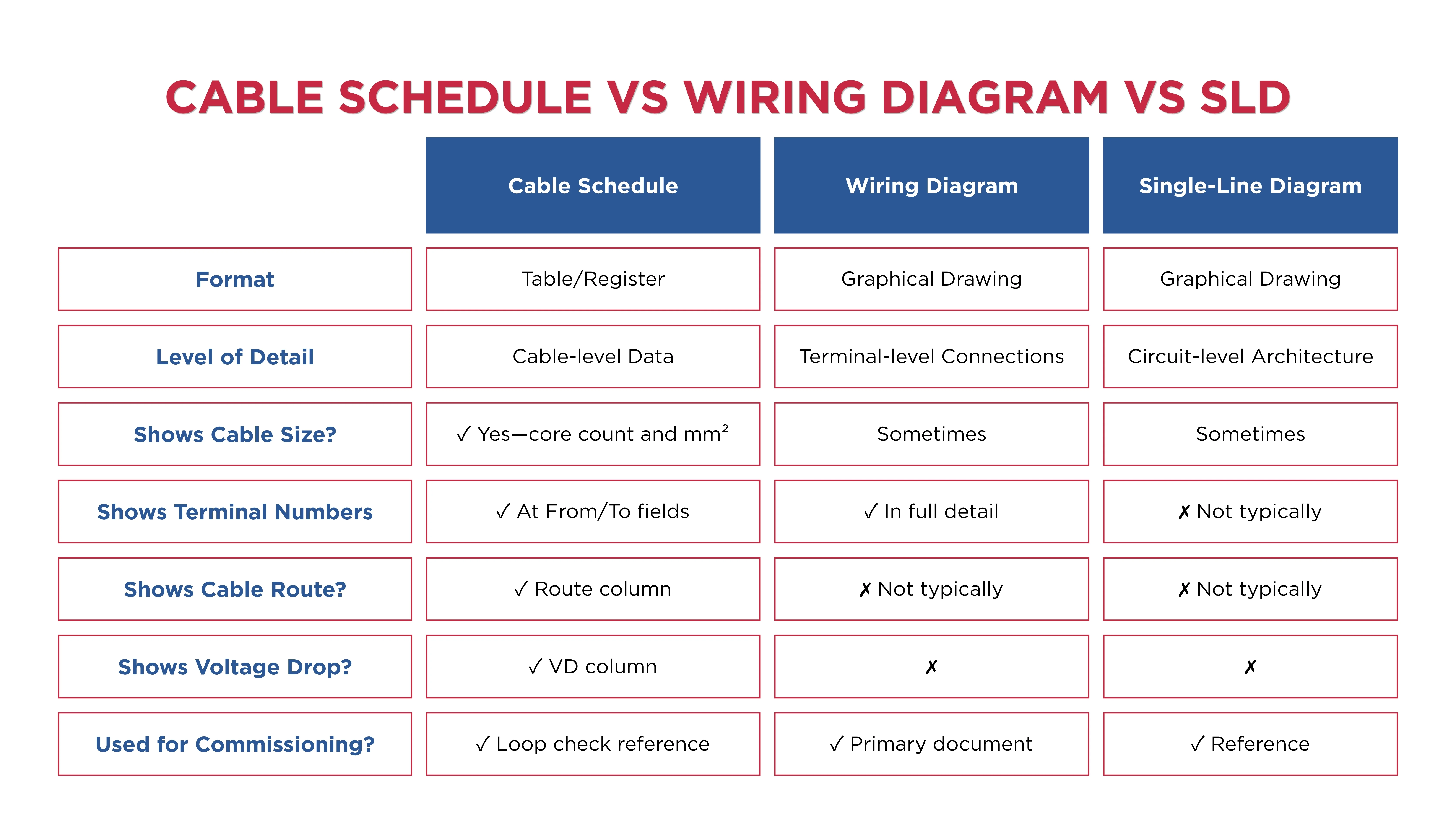
Single-Line Diagram: Every power cable in the cable schedule should correspond to a circuit on the SLD. The cable number on the schedule should match the cable tag on the SLD. The conductor size in the schedule should match the specification shown on the SLD. Any discrepancy between the cable schedule and the SLD indicates an error in one or both documents.
Wiring Diagrams and Loop Drawings: Instrumentation and control cables in the schedule are cross-referenced to wiring diagrams and loop drawings that show the terminal-level connections.
Cable Tray Layout and Routing Drawings: The route column in the cable schedule references the cable tray layout drawings that show where trays are installed and which trays each cable travels through. Discrepancies between the schedule route and the actual tray layout are a common source of cable pulling errors.
Cable Sizing Calculations: The conductor size and voltage drop columns in the schedule must be consistent with the cable sizing calculations. On AS/NZS 3008 compliant Australian projects, every cable in the power schedule should be traceable to a cable sizing calculation that confirms the selected size satisfies current-carrying capacity, voltage drop, and short-circuit withstand requirements.
Material Take-Off: Cable schedule is a reference in preparing Material Take-Off of cable for procurement. The cable type, size, and estimated length columns are the inputs to the cable drum schedule.
How Are Cable Schedules Used Across the Project Lifecycle?
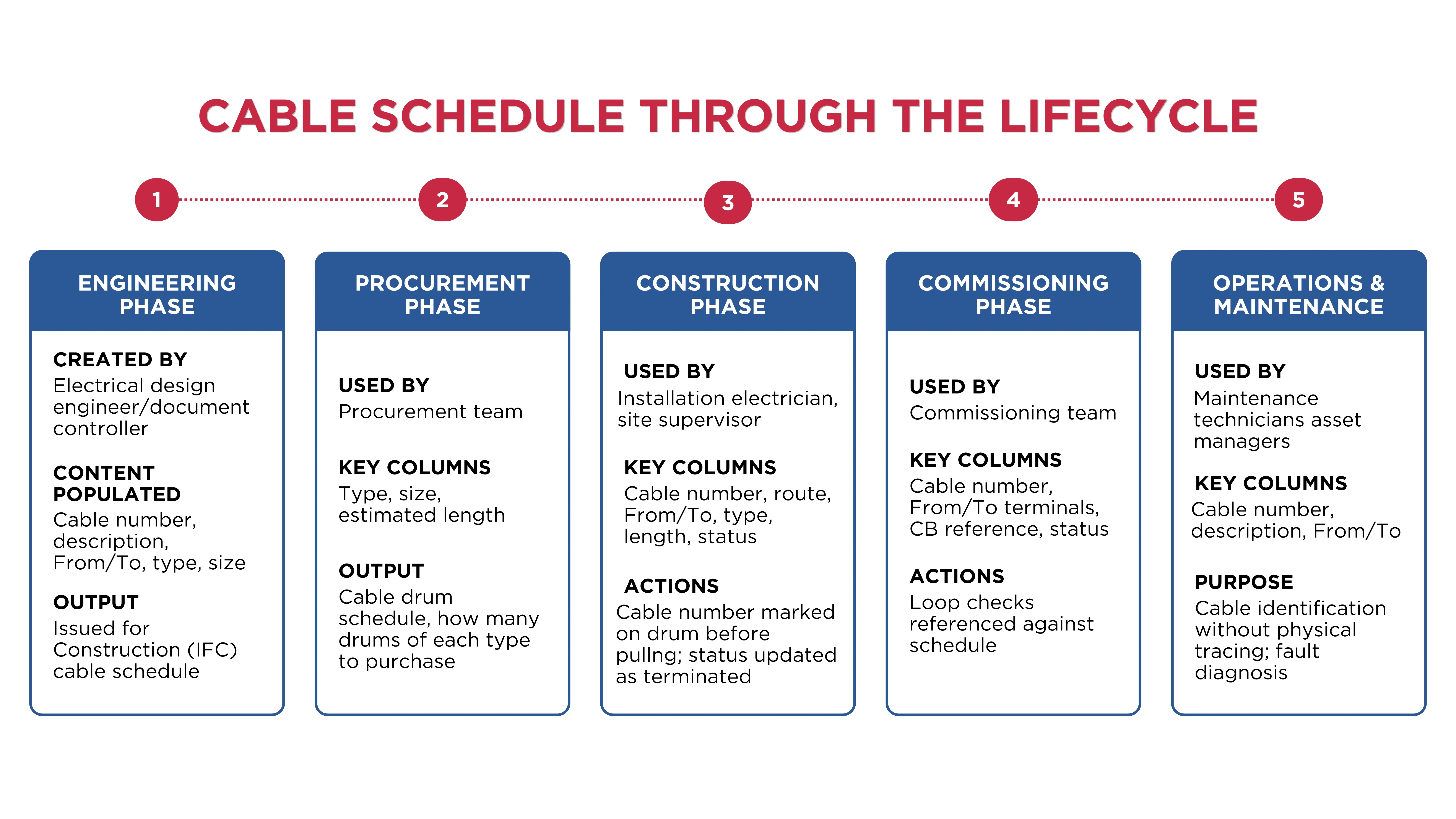
The cable schedule acts as a master reference throughout the engineering, procurement, construction, commissioning, and maintenance phases of a project.
Engineering: Cable schedule is prepared by the design team from the SLD and load list. Cable sizing calculations populate the size column. The schedule is issued for review and subsequently for construction.
Procurement: Cable types, sizes, and estimated lengths drive the cable drum procurement schedule. The schedule determines how many drums of each type are purchased and when they need to be on-site.
Construction: Construction teams use the cable schedule to plan cable pulling sequences, confirm cable routes before pulling, verify drum numbers against schedule entries before cutting, and update the status column as cables are pulled and terminated.
Commissioning: During commissioning, it helps engineers perform loop checks and signal verification. Commissioning engineers reference the cable schedule to confirm cable identification, protective device details, and terminal numbers during continuity testing and function testing.
Maintenance and Operations: During maintenance, technicians can quickly identify cables without tracing them physically. It also helps during plant expansion and modification projects. The cable schedule is one of the most-referenced documents in the O&M package for the life of the installation.
Generate Accurate Cable Schedules with CableHero
Preparing a cable schedule manually is time-consuming and creates compliance risk when data is entered inconsistently across different circuits.
CableHero is an electrical design platform that automatically generates real-time cable schedules from your cable sizing calculations. With CableHero, you can:
Generate cable schedules automatically from your circuit inputs
Ensure AS/NZS 3008 and AS/NZS 3000 compliance for every circuit in the schedule
Export branded PDF cable schedules ready for client submission, certification, or construction issue
Update schedules instantly when a circuit is changed
For Australian electrical designers and engineers who produce cable schedules regularly, CableHero eliminates the risk of inconsistency between the cable sizing calculation and the schedule it produces. Try it today for free.
FAQ
What is the difference between a cable schedule and a wiring diagram?
A cable schedule is a tabular document that records key data about every cable in an installation: its unique number, specification, size, route, length, From/To connections, and compliance status. It is used for procurement, construction planning, commissioning verification, and maintenance reference.
What information should a cable schedule always include for AS/NZS 3000 compliant Australian installations?
For Australian power electrical projects, a compliant cable schedule should include:
A unique cable number or tag
A description of the circuit or service
From and To locations and terminal references
Cable type and voltage rating
Number of cores and conductor cross-sectional area in mm²
Installation method and route reference
Estimated cable length including termination slack and procurement contingency
How do you verify a cable schedule is accurate before construction starts?
Verifying a cable schedule before construction requires cross-checking it against the other key project documents. Check that every cable in the schedule has a corresponding circuit on the single-line diagram, with matching From/To references and cable specification. Verify that the conductor sizes in the schedule are consistent with the cable sizing calculations.


 Cable Sizing