Every electrical installation in Australia starts with the same document: the AS/NZS 3000 Wiring Rules. This is the standard that governs how electrical systems must be designed, installed, and verified, from a single residential circuit to a multi-storey commercial building.
For cable sizing specifically, the AS3000 Wiring Rules don't just set a minimum. They set a framework: three interdependent checks that every cable must pass to be compliant.
This guide explains what the AS3000 Wiring Rules actually require for cable sizing, with the clause references and calculations that engineers and electricians use every day.
What Are the AS3000 Wiring Rules?
AS/NZS 3000:2018, formally titled Electrical Installations and universally known as the Wiring Rules, is the joint Australian and New Zealand standard for electrical installations. It sets the minimum requirements for the design, construction, and verification of all low-voltage electrical systems operating up to 1,000 V AC or 1,500 V DC.
The standard is published jointly by Standards Australia and Standards New Zealand. In Australia, it is referenced directly in state and territory electrical safety legislation, making compliance legally mandatory, not optional.
The current edition is AS/NZS 3000:2018, with three published amendments. Any new installation or modification must be designed and certified to the current amended version.
The AS3000 Wiring Rules cover:
Earthing and bonding
Maximum demand calculation
Wiring methods
Switchboard construction
RCD protection
Protection devices
Testing and verification
How Do the AS3000 Wiring Rules and AS/NZS 3008 Work Together?
The AS3000 Wiring Rules and AS/NZS 3008.1.1 work as a pair. You cannot correctly apply one without the other in cable sizing. You use the Wiring Rules to know what's required, and AS/NZS 3008 to calculate whether your cable meets it. The most recent edition of AS/NZS 3008.1.1 is the 2025 edition, which expanded DC cable sizing coverage (relevant for solar PV and battery storage), updated multi-row grouping correction factors, and harmonised the standard ambient temperature reference at 40°C for all in-air installations across Australia.
What Is the Three-Check Cable Sizing Method Under AS3000?
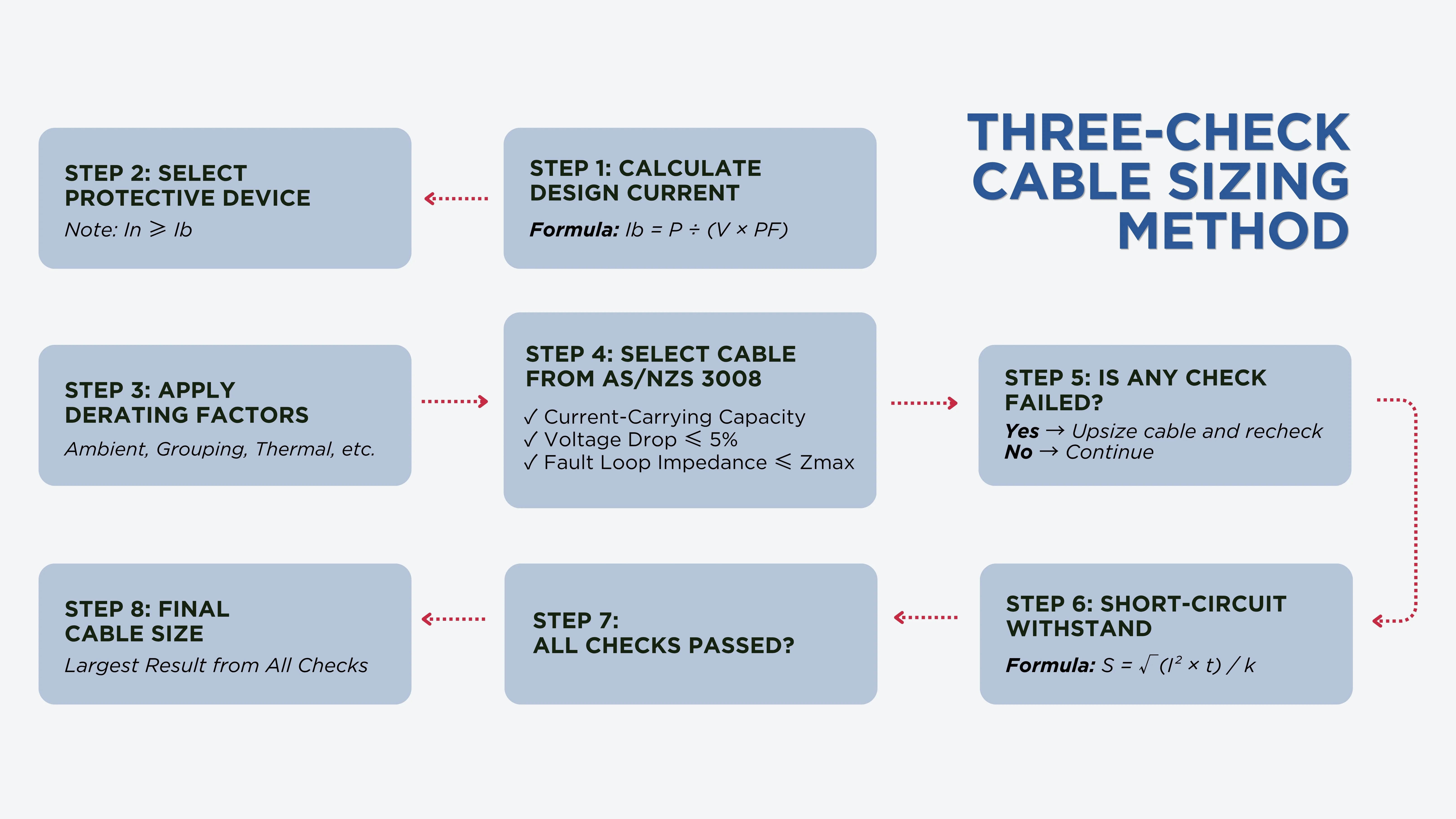
Every cable in an Australian electrical installation must pass three separate checks under the AS3000 Wiring Rules and AS/NZS 3008.1.1. The final cable size is determined by the largest result from all three, whichever check produces the biggest required cross-section governs.
Check 1: Current-Carrying Capacity
The cable must carry the full design current continuously without exceeding its insulation temperature rating. The cable sizing inequality from AS/NZS 3000 Clause 3.3 is: Ib ≤ In ≤ Iz.
Ib = Design current of the circuit (A)
In = Rated current of the protective device (A)
Iz = Current-carrying capacity of the cable after all derating (A)
For circuit breakers, an additional condition applies: I₂ ≤ 1.45 × Iz.
Iz = Current ensuring effective operation of the breaker
This condition prevents the scenario where the breaker can carry more than the cable can handle before tripping.
The base current ratings come from AS/NZS 3008.1.1 Tables 3–12 for copper and aluminium conductors with various insulation types. These ratings assume a single isolated cable at the standard reference temperature and must be corrected for actual installation conditions using derating factors.
Check 2: Voltage Drop
The voltage drop from the origin of the installation (main switchboard) to the furthest point of utilisation must not exceed 5% of the nominal supply voltage under AS/NZS 3000 Clause 3.6.
For a 230 V single-phase supply, the limit is 11.5 V. For 400 V three-phase, the limit is 20 V. This is a cumulative limit across all circuit segments.
Voltage drop is calculated using the mV/A/m impedance values from AS/NZS 3008.1.1 Tables 30–42. For circuits with inductive loads or large conductors, both resistance and reactance components must be considered. On longer runs, voltage drop is often the governing factor that forces cable upsizing above what current-carrying capacity alone would require.
Check 3: Fault Loop Impedance (Earth Fault Loop)
The total fault loop impedance (Zs) must be low enough that the protective device disconnects within the required time under AS/NZS 3000:
0.4 seconds for final subcircuits supplying socket outlets and portable equipment
5 seconds for submains, distribution circuits, and circuits supplying fixed equipment
Zs = Ze + Zint
Ze = External supply impedance
Zint = Combined resistance of the active and protective earth conductors
A cable that passes the current-carrying and voltage drop checks may still fail the fault loop impedance check, particularly on longer runs where earth conductor resistance becomes significant. The governing rule: whichever of the three checks produces the largest required cable cross-section determines the minimum compliant cable size.
What Are the Key AS3000 Wiring Rules Clauses for Cable Sizing?
Several clauses in AS/NZS 3000:2018 directly govern how cables are selected and sized. These are the ones that appear most frequently in design calculations, inspection reports, and compliance certifications.
Clause 3.3: Cable Selection and Current-Carrying Capacity
This is the gateway clause that links the Wiring Rules to AS/NZS 3008 for cable sizing. It establishes the fundamental requirement that cables must be selected based on their current-carrying capacity under the actual installation conditions, not the rated capacity of the cable in isolation.
Clause 3.3 is where the Ib ≤ In ≤ Iz inequality is established, and where the requirement to apply derating factors from AS/NZS 3008 is mandated.
Any cable sizing that does not account for derating is non-compliant with Clause 3.3, regardless of whether the cable's base rating exceeds the design current.
Clause 3.3.2.13 specifically addresses cables passing through bulk thermal insulation. The current-carrying capacity must be calculated according to the length of cable passing through the insulation, not just the general installation method.
Clause 3.5: Protection Against Overcurrent
Clause 3.5 covers the requirements for overload and short-circuit protection. Every cable must be protected by a device that:
Has a rated current no less than the circuit's design current
Has a rated current no greater than the cable's rated current-carrying capacity
Will disconnect the circuit in the event of a short circuit before thermal damage occurs to the cable
This last point is the third constraint on cable sizing that many designers overlook. A cable must carry its normal load current and maintain voltage drop within limits. It must also survive the thermal stress of a short-circuit fault for the time it takes the protective device to clear the fault.
The adiabatic equation from AS/NZS 3008.1.1 determines the minimum conductor cross-section to withstand short-circuit current: S = √(I² × t) / k.
S = Minimum conductor cross-section (mm²)
I = Fault current (A)
t = Disconnection time (s)
k = Material constant: 143 for copper/PVC at 75°C, 176 for copper/XLPE at 90°C
On circuits close to large transformers or substations, the adiabatic requirement frequently governs the minimum earth conductor size, and sometimes the active conductor as well.
Clause 3.6: Voltage Drop
Clause 3.6 (and Clause 3.5.1 in the 2018 edition) establishes the 5% voltage drop limit from the origin of the installation to the furthest point of utilisation. The key compliance points:
The 5% is a cumulative total, not a per-segment allowance
Best practice allocates approximately 0.5–2% to consumer mains, 1.5–2% to submains, and the remainder to final subcircuits
For lighting circuits, Clause 3.6 guidance recommends limiting drop to 3% to avoid perceptible dimming
For solar PV installations, AS/NZS 4777.1 limits the voltage rise (not drop) on the AC cable between the inverter and the point of supply to 2%
This clause establishes the adiabatic method for sizing protective earth conductors, ensuring they can carry fault current for the protective device's clearing time without thermal damage. Combined with the fault loop impedance check, this clause produces the minimum earth conductor size for any circuit.
Earth conductor sizing has two constraints that both apply:
Fault Loop Impedance: The earth conductor must be large enough that Zs ≤ Zmax
Adiabatic Withstand: The earth conductor must carry the fault current for the clearing time without exceeding its short-circuit temperature limit
The larger of the two results governs. Designers who only check one produce undersized earth cables. This is a compliance failure that typically only surfaces during the earth fault loop impedance test at commissioning.
Table 3.3: Minimum Conductor Cross-Sections
AS/NZS 3000:2018 Table 3.3 sets the absolute minimum conductor sizes regardless of the sizing calculation. For standard PVC-insulated fixed wiring, the minimum is:
1.5 mm² for lighting and general purpose circuits (fixed wiring)
2.5 mm² for power circuits and final subcircuits supplying socket outlets
1.0 mm² for flexible cords and leads
These minimums apply even when the calculated requirement would be smaller. No cable used in a fixed installation may be smaller than the Table 3.3 minimum for its application.
When Does the AS3000 Wiring Rules Require Cable Upsizing?
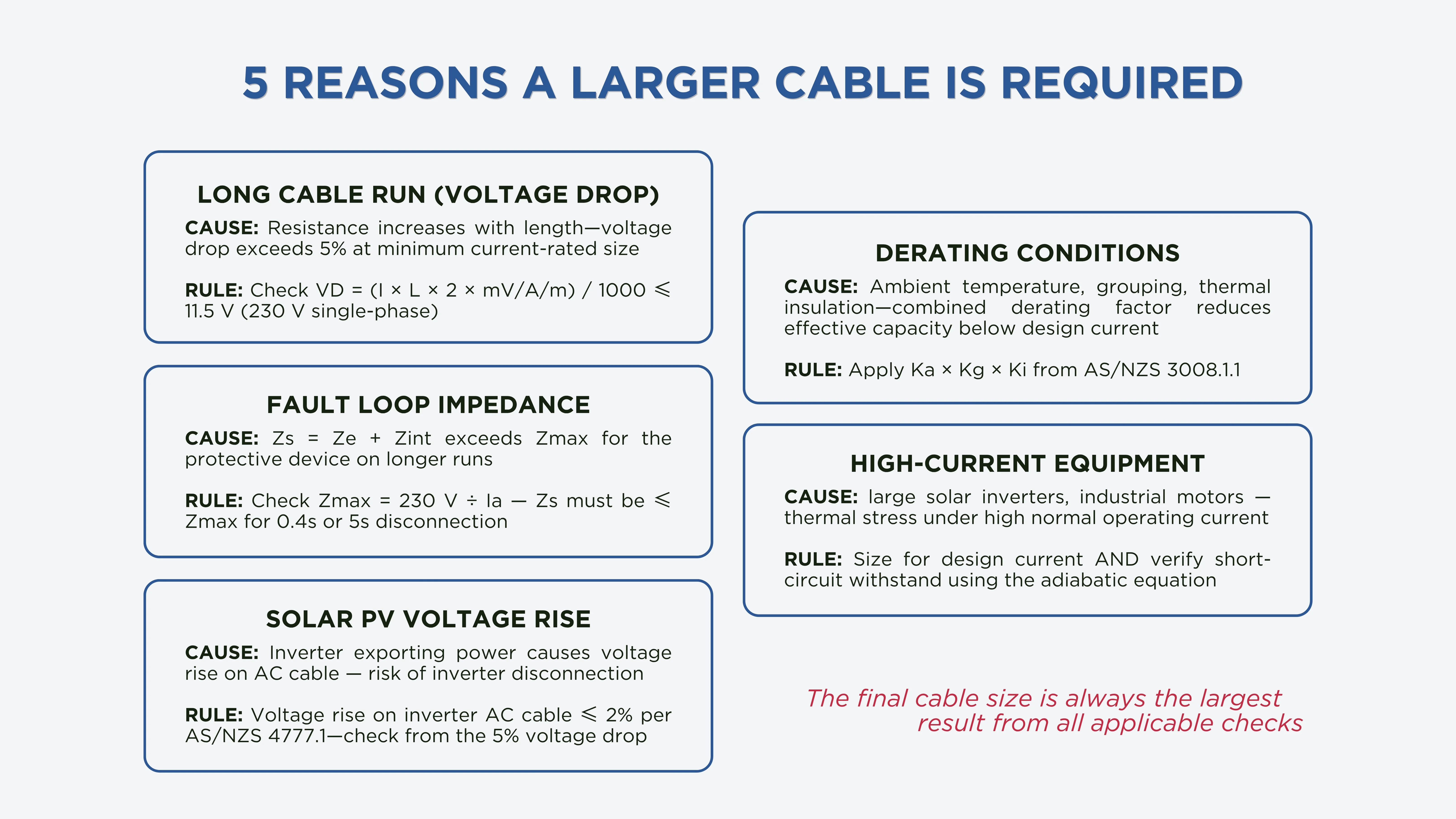
Under the three-check method, there are five specific scenarios where a cable must be upsized above the minimum that current-carrying capacity alone would suggest.CEdit.7.4.webp481.26 KB
Long Cable Runs and Voltage Drop
This is the most common reason for upsizing. As cable length increases, resistance increases linearly, and voltage drop increases proportionally.
For example, on a 230 V single-phase circuit with a 20 A load and a 35-metre run using 2.5 mm² copper (mV/A/m ≈ 18.1 mV/A/m):
VD = (20 × 35 × 2 × 18.1) / 1000 = 25.3 V = 11% — more than double the 5% limit.
Upsizing to 4 mm² (mV/A/m ≈ 11.2) brings the drop to 15.7 V = 6.8%. Still over the limit. The circuit requires 6 mm² to comply, despite the 2.5 mm² cable being adequate for the current.
Derating Due to Installation Conditions
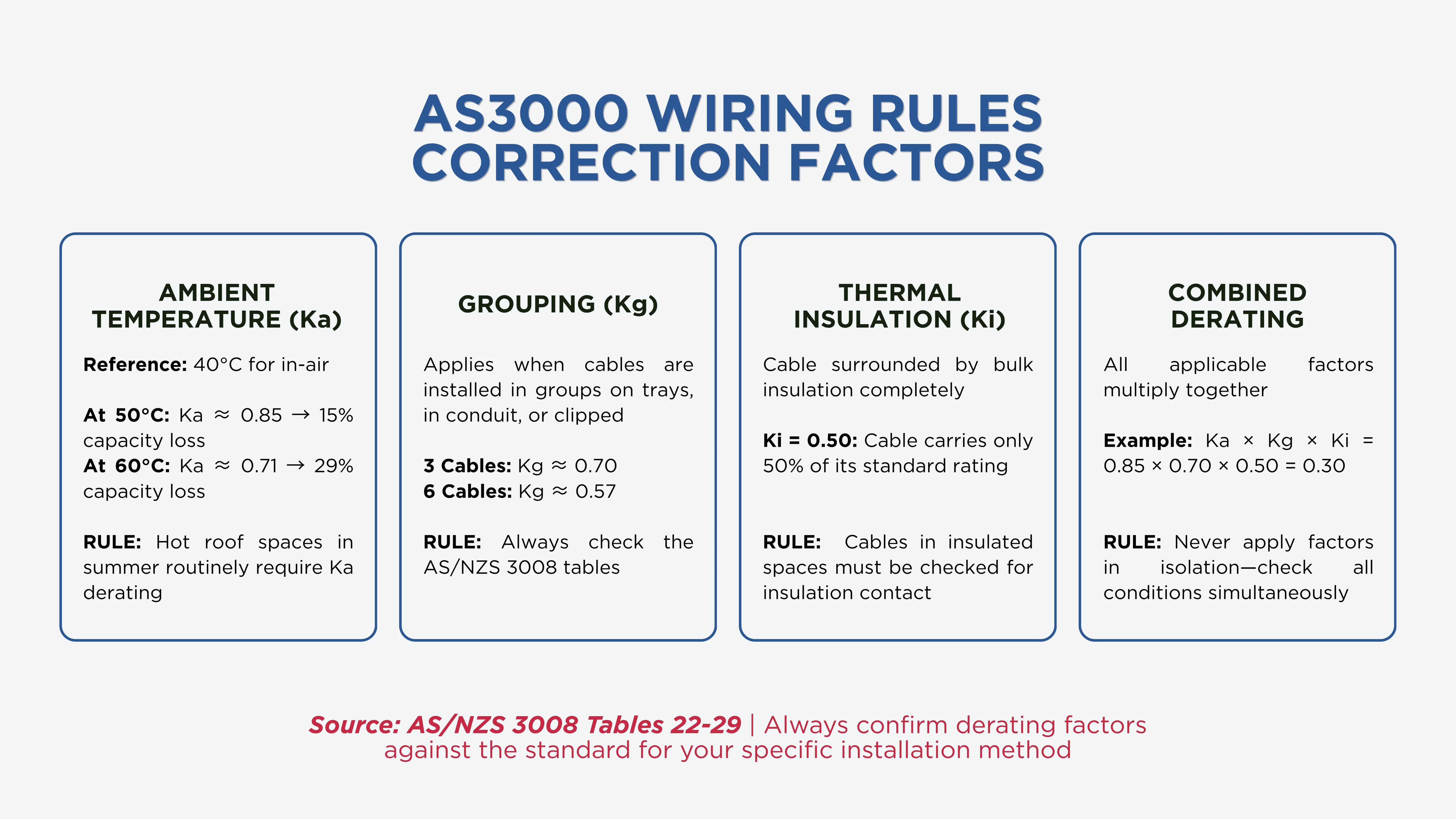
Cables operating at elevated ambient temperatures, grouped with other loaded cables, buried in poor-conductivity soil, or enclosed in thermal insulation all have reduced current-carrying capacity. This is handled through derating factors from AS/NZS 3008.1.1 Tables 22–29.
The derated current-carrying capacity is calculated as:
Iz = It × Ka × Kg × Ki (× other applicable factors)
Ka = Ambient temperature correction factor
Kg = Grouping factor
Ki = Thermal insulation factor
In each case, the derated Iz must still satisfy Ib ≤ In ≤ Iz. If the design current is 20 A and grouping reduces Iz to 17 A, the cable must be upsized to restore the required capacity.CEdit.7.3.webp411.37 KB
Fault Loop Impedance on Long Runs
On longer circuits, the combined resistance of the active and earth conductors may push Zs above the maximum permitted Zmax for the protective device. This requires upsizing the earth conductor to bring Zs within limits.
This check becomes critical on industrial installations, rural properties, and submain runs in multi-storey buildings where cable runs may reach 40–100 metres or more.
High-Current Equipment
Equipment like electric vehicle chargers (typically 32–63 A per circuit), large solar inverters, industrial motors, and commercial HVAC systems creates circuits with high design currents. These loads require larger conductors not just for current-carrying capacity but to manage the thermal stress under normal operation and during fault conditions.
For high-current circuits, the short-circuit withstand check becomes increasingly relevant, particularly for earth conductors where the prospective fault current at the switchboard is high.
Solar PV Voltage Rise
In solar PV installations, the requirement is inverted from the usual voltage drop concern. AS/NZS 4777.1 limits voltage rise on the AC cable from the inverter to the point of supply to 2%. When a solar inverter is exporting power, voltage rises from the inverter toward the grid.
If the cable is too small, this rise can trigger inverter disconnection, reducing system output and potentially causing compliance failures.
The upsizing requirement for voltage rise on solar AC cables is separate from the standard 5% voltage drop check and is commonly misunderstood or overlooked on residential and small commercial solar installations.
What Are the Key Changes in the 2018 Edition of the AS3000 Wiring Rules?
Understanding what changed in the 2018 edition (and its subsequent amendments) matters for designers certifying new work and for electricians modifying existing installations.
RCD Requirements Expanded. RCD with a maximum rated residual current of 30 mA are now required for all final subcircuits in domestic and residential installations. For commercial and industrial installations, RCDs are required for final subcircuits rated 32 A or less supplying socket outlets, lighting, and direct-connected handheld equipment.
Thermal Insulation Derating Formalised. Clause 3.3.2.13 now explicitly addresses cables passing through bulk thermal insulation, with current-carrying capacity calculated according to the length of cable in the insulation per AS/NZS 3008.1.
EV Charging Provisions Added. Appendix P provides guidance on EV socket outlet and charging station installation. EV charging loads are now included in Appendix C maximum demand calculations under Table C1 and C2.
AFDDs Introduced. Arc Fault Detection Devices are required in New Zealand for final subcircuits up to 20 A in locations with significant fire risk. Not currently mandatory in Australia, but the provisions are included in the standard.
RCD and EFLI Testing Clarified. Clause 8 testing requirements for earth fault loop impedance and RCD testing have been updated, with clearer guidance on measurement methods and documentation requirements.
How Do You Apply the AS3000 Wiring Rules for Cable Sizing?
Applying the AS3000 Wiring Rules correctly to a cable sizing task follows a structured sequence:
Step 1: Determine the Design Current (Ib) — Calculate Ib from the load: for a single-phase load, Ib = P / (V × PF). For a three-phase load, Ib = P / (√3 × V × PF).
Step 2: Select a Protective Device (In) — Choose a protective device with In ≥ Ib. The device type and rating determine the Ia value used for the fault loop impedance check.
Step 3: Apply Derating Factors — Identify all applicable installation conditions: ambient temperature, grouping, thermal insulation. Calculate the combined derating factor and the required un-derated cable rating: It = Ib / (Ka × Kg × Ki × ...)
Step 4: Select Cable from AS/NZS 3008 Tables — Find the smallest standard cable size with a base current rating ≥ It. This is your initial selection from the current-carrying capacity check.
Step 5: Check Voltage Drop — Calculate voltage drop using the mV/A/m values for your chosen cable. If VD exceeds 5% (total, cumulative from origin), upsize to the next standard cable size and recheck.
Step 6: Check Fault Loop Impedance — Calculate Zs = Ze + Zint for the chosen cable and earth conductor. Compare against Zmax = Uo / Ia for the protective device and required disconnection time. If Zs > Zmax, upsize the earth conductor and recheck.
Step 7: Check Short-Circuit Withstand — Verify that both the active and earth conductors can withstand the prospective fault current for the device clearing time without exceeding the short-circuit temperature limit.
Step 8: Select the Governing Cable Size — The final cable size is the largest result from Steps 4, 5, 6, and 7. All four checks must be satisfied simultaneously.
Size Cables With Confidence Using CableHero
Applying the AS3000 Wiring Rules correctly to every cable in an installation means running three checks, applying every relevant derating factor, and tracking the cumulative voltage drop budget across all circuit segments. Doing this by hand for a complex installation is time-consuming, error-prone, and hard to document.
CableHero is a cable sizing software fully aligned with AS/NZS 3000:2018 and AS/NZS 3008.1.1 (including the 2025 edition). With CableHero, you can:
Run all three AS3008 checks simultaneously — current-carrying capacity, voltage drop, and fault loop impedance — for any circuit.
Apply derating factors automatically for ambient temperature, grouping, burial depth, and thermal insulation.
Track cumulative voltage drop across consumer mains, submains, and final subcircuits — so you never exceed the 5% total.
Size earth conductors for both fault loop impedance and adiabatic withstand.
Generate compliant PDF cable schedules and reports ready for certification and DNSP submission.
Whether you're designing a residential fit-out, a commercial floor, or a large-scale solar installation, CableHero takes the calculation burden off your hands. Try it for free today.
FAQ
What are the AS3000 Wiring Rules and are they legally mandatory in Australia?
The AS3000 Wiring Rules are the joint Australian and New Zealand standard governing the design, construction, and verification of electrical installations. They are legally mandatory in Australia, with each state and territory referencing it in its electrical safety legislation, making compliance a legal obligation for all licensed electrical installation work.
What is the three-check cable sizing method under the AS3000 Wiring Rules?
Under the AS3000 Wiring Rules and AS/NZS 3008, every cable must pass three separate checks: (1) current-carrying capacity, (2) voltage drop, and (3) fault loop impedance.
When do the AS3000 Wiring Rules require cable upsizing above the minimum?
Cable upsizing is required whenever any of the three cable sizing checks produces a larger minimum cross-section than current-carrying capacity alone would suggest. The most common situations are: long cable runs, heavily derated circuits, and circuits where fault loop impedance or short-circuit withstand.


 Cable Sizing