Voltage Drop Calculations for Long Cable Runs: A Practical Guide
Voltage drop becomes the controlling constraint on long cable runs. This guide walks through every calculation method under AS/NZS 3008.1.1:2025, with worked examples and practical fixes for circuits that exceed the AS/NZS 3000 limit.
On short cable runs, voltage drop is rarely the problem. Pick a cable for current-carrying capacity, verify it quickly, move on. However, as cable runs extend, voltage drop stops being a secondary check and starts being the primary constraint. It forces cable sizes far larger than current-carrying capacity alone would ever require. This catches designers and electricians out regularly, because the calculation is easy to skip when the load is modest and the current check passes comfortably. The consequences of getting it wrong are real. × Equipment receives insufficient voltage and underperforms. × Motors run hot and fail prematurely. × Lighting dims below usable levels. × A fault downstream cannot generate enough current to trip the protective device. This guide covers voltage drop on long cable runs in full, the three calculation methods available in AS/NZS 3008.1.1:2025, worked examples for single-phase and three-phase circuits, and the practical fixes when a circuit exceeds the limit.
What Is Voltage Drop and Why Does It Matter?
When current flows through a conductor, it encounters resistance. That resistance converts some electrical energy to heat, reducing the voltage available at the load end of the circuit. The voltage at the load is always lower than at the supply. The difference is the voltage drop.
The problem with voltage drop is it may cause equipment to malfunction. It reduces potential energy available at the load, and it results in energy loss dissipated as heat in the cable.
On long cable runs, these effects are amplified. Voltage drop increases linearly with length. Doubling the circuit length doubles the drop. This is the primary driver on rural, warehouse, and large-format commercial installations.
What Are the Australian Voltage Drop Limits?
Australia's voltage drop limits are governed by two standards working together.
AS/NZS 3000 (the Wiring Rules) sets the maximum permissible voltage drop from the point of supply to any point of utilisation. AS/NZS 3008.1.1 provides the cable impedance data needed to calculate whether a given cable and run length satisfies those limits.
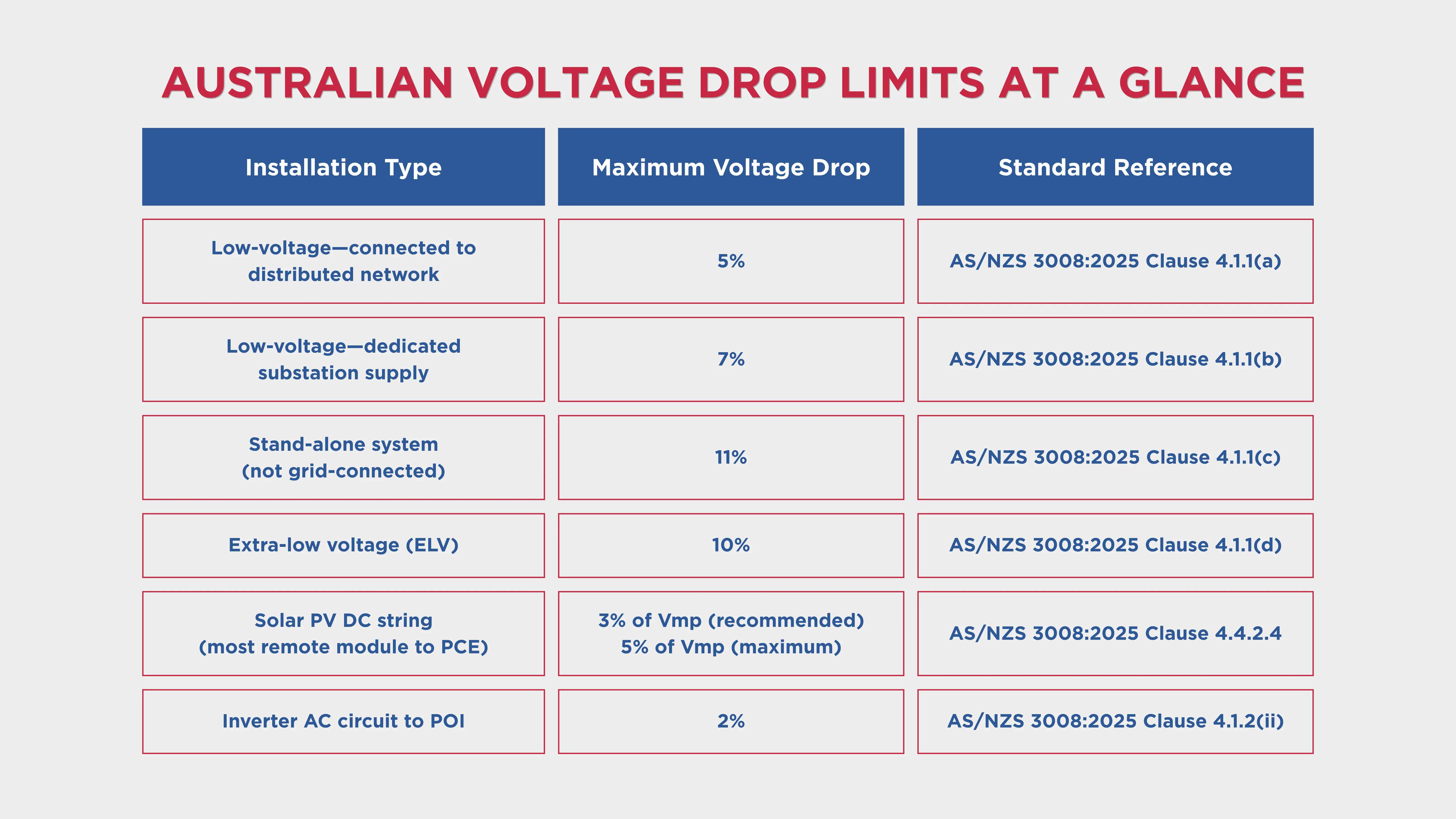
The voltage drop limits in AS/NZS 3008.1.1:2025 are:
5% for low-voltage installations connected directly to a distributed low-voltage network
7% for low-voltage installations supplied from a dedicated substation
10% for extra-low-voltage installations
3% for PV arrays from the most remote PV module to the input of the PCE under maximum load conditions (AS/NZS 5033:2021)
2% for inverter AC circuits to the point of supply where no high-export-voltage protection is provided
For the vast majority of Australian residential and commercial installations connected to the DNSP network, the limit is 5% from the point of supply to the load. This represents a maximum of 11.5 V on a 230 V single-phase circuit and 20 V on a 400 V three-phase circuit.
Best practice is to keep voltage drop below 3% where possible for optimal equipment performance, with 5% as the hard ceiling.
This 5% is cumulative. It applies to the total drop from the supply origin to the furthest load, across all series cable sections. A consumer main consuming 2% and a final sub-circuit consuming 4% produces a 6% total. This is non-compliant, even if neither section exceeded its individual budget.
What Are the Three Voltage Drop Calculation Methods in AS/NZS 3008?
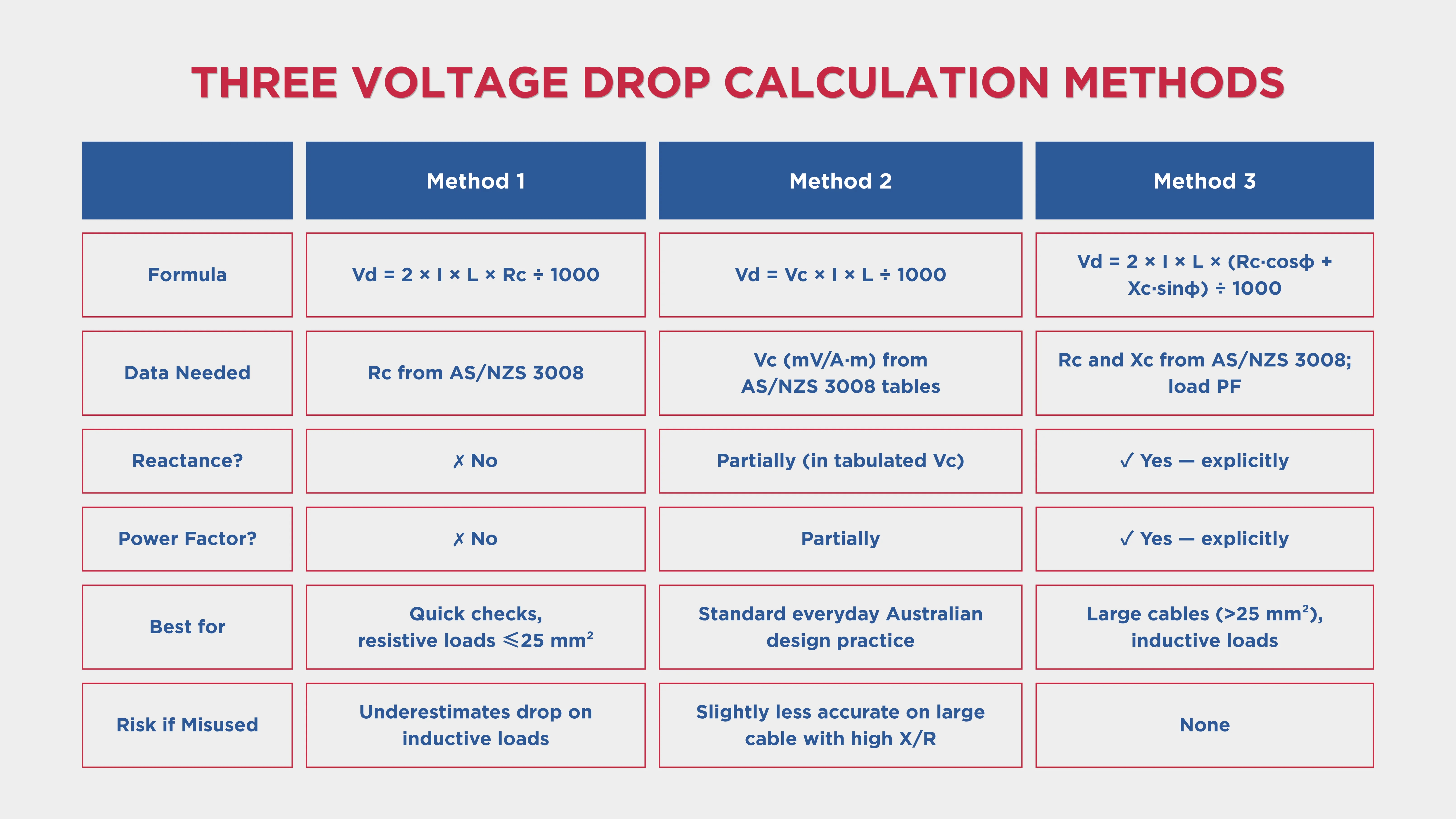
There are three approaches to voltage drop calculation in AS/NZS 3008, varying in complexity and accuracy.
Method 1: Simple Resistance Method (Quick Check)
The simplest approach applies the fundamental relationship between resistance, current, and voltage: Single-phase: Vd = 2 × I × L × Rc ÷ 1000 | Three-phase: Vd = √3 × I × L × Rc ÷ 1000
Vd = Voltage drop in volts
I = Design Current in amps
L = One-way cable length in metres
Rc = Conductor AC resistance at operating temperature in Ω/km
Factor of 2 accounts for active and neutral conductors in single-phase circuits
This method is useful for quick checks and simple, purely resistive circuits. It does not account for cable reactance or power factor, so it can underestimate voltage drop in circuits with inductive loads or large conductors.
It is reliable for smaller cables (up to approximately 16–25 mm²) with resistive loads such as heating elements and incandescent lighting.
Method 2: The mV/A·m Method (Standard Australian Practice)
This is the method most commonly used in Australian electrical design and directly supported by the tables in AS/NZS 3008.
Single-Phase: Vd = Vc × I × L ÷ 1000
Three-Phase: Vd = Vc × I × L ÷ 1000
Where Vc is the voltage drop constant in mV/A·m, obtained from the relevant AS/NZS 3008 table for the cable size, type, and installation method.
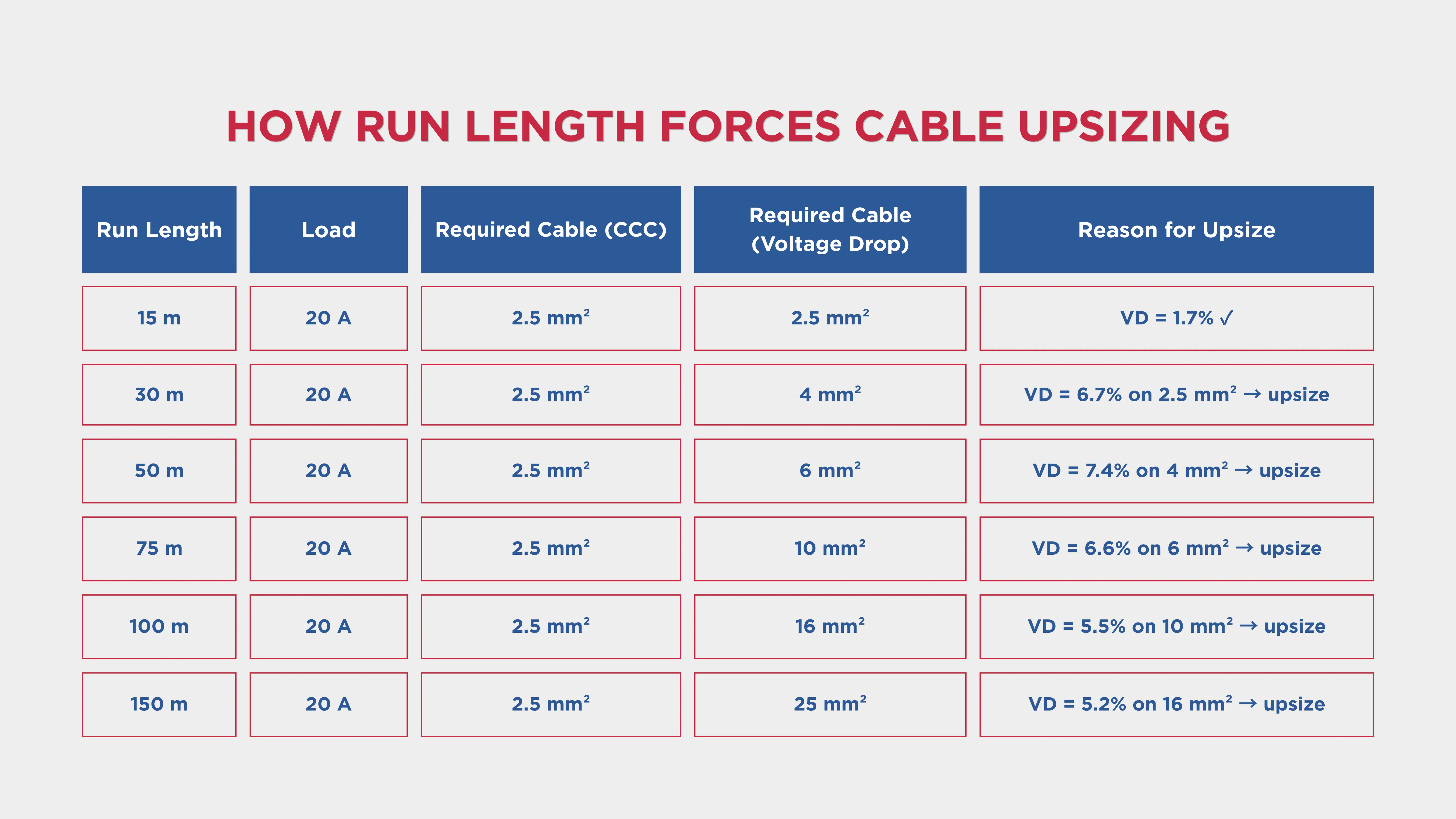
The mV/A·m values in AS/NZS 3008 are tabulated at the conductor's rated operating temperature and incorporate the standard installation conditions. This is the most practical method for everyday use without requiring separate resistance and reactance lookups. This is the upsizing cascade that long cable runs produce. The cable for current-carrying capacity (2.5 mm²) ends up needing to be 10 mm² or larger to satisfy voltage drop.
Method 3: Power Factor Method
For commercial and industrial circuits, the power factor method gives the most accurate result:
Single-phase: Vd = 2 × I × L × (Rc·cosφ + Xc·sinφ) ÷ 1000
Three-phase: Vd = √3 × I × L × (Rc·cosφ + Xc·sinφ) ÷ 1000
Where:
Rc = AC resistance of conductor at operating temperature (Ω/km)
Xc = Conductor reactance (Ω/km)
cosφ =Load power factor
sinφ = √(1 − cosφ²)
This method matters most for large conductors.
For a three-phase motor feeder at 0.85 PF, sinφ = 0.527. The reactance term (Xc × sinφ) is not negligible on cables above 35 mm². Using Method 1 or 2 without accounting for it can produce a calculation that passes on paper but fails in reality.
What Drives Voltage Drop on Long Cable Runs?
Understanding the variables lets you make targeted design decisions.
Cable Length: Voltage drop is directly proportional to current, so circuits close to their rated capacity will show maximum drop. Doubling the run length doubles the drop.
Load Current: This is directly proportional to voltage drop. Diversity is a legitimate tool for reducing the design current used in voltage drop calculations, but it must be justified.
Cable Cross-Sectional Area: This is the primary lever for reducing voltage drop. Moving to the next standard cable size reduces conductor resistance proportionally.
Conductor Material: Copper has lower resistance than aluminium for the same cross-sectional area. Aluminium cables typically need to be larger than copper cables to achieve the same voltage drop performance.
Power Factor: Lower power factor increases the reactive component of voltage drop, particularly in larger cables with significant reactance.
Voltage Drop on Long Cable Runs on Solar PV String and Array Cables
AS/NZS 5033:2021 Clause 4.4.2.4 requires the voltage drop from the most remote PV module in the array to the input of the PCE to not exceed 5% of Vmp (at STC).
For string cables operating in a DC circuit, the voltage drop formula uses DC resistance values. These are now provided in dedicated DC tables in AS/NZS 3008.1.1:2025. The 3% target in AS/NZS 5033 represents 24 V on an 800 V string. On long string cable runs in large solar installations, this limit is routinely exceeded with smaller cable sizes, requiring upsizing to 6 mm² or larger.
How Is a Long Cable Run that Exceeds the Voltage Drop Limit Fixed?
When a voltage drop calculation fails the AS/NZS 3000 5% limit, these are the available solutions:
Upsize the Conductor. Moving to the next standard cable size directly reduces resistance per metre. On very long runs, multiple upsizing steps may be required.
Shorten the Cable Run. Relocating the distribution board or sub-switchboard closer to the load reduces circuit length.
Switch from Aluminum to Copper. If an aluminium submain exceeds the voltage drop limit, switching to copper of the same cross-section reduces drop by approximately 40%.
Split the Load Across Multiple Circuits. Distributing load across two or more smaller circuits reduces the current in each.
Use Parallel Cables. Two parallel cables of the same size effectively halve the impedance and therefore halve the voltage drop.
Improve Load Power Factor. For inductive loads where power factor correction equipment is available, improving power factor reduces the reactive component.
Calculate Voltage Drop on Long Cable Runs with CableHero
Manual voltage drop calculations on long cable runs take time and create risk. One missed cumulative addition or wrong table reference and the result is non-compliant.
CableHero is Australia's purpose-built cable sizing and electrical design platform, built specifically for AS/NZS 3008.1.1:2025 and AS/NZS 3000 compliance.
With CableHero's voltage drop calculator, you can:
Calculate voltage drop instantly for single-phase, three-phase, and DC circuits using the accurate power factor method from AS/NZS 3008.1.1:2025
Track cumulative voltage drop across consumer mains, sub-mains, and final subcircuitt
Apply power factor corrections automatically for inductive motor and mixed loads
Identify the controlling constraint before selecting a cable
Generate compliant PDF reports ready for certification and DNSP submission
For Australian electricians and engineers who regularly deal with long cable runs, CableHero eliminates the risk of missed cumulative calculations and incorrect table references.
What is the maximum voltage drop allowed on a long cable run in Australia?
The maximum voltage drop from the point of supply to any point of utilisation is 5% for low-voltage installations connected directly to a distributed low-voltage network, per AS/NZS 3008.1.1:2025 Clause 4.1.1(a).
Why does voltage drop force larger cables on long runs than current-carrying capacity alone?
This is because voltage drop scales linearly with cable length while current-carrying capacity is independent of length. The only way to reduce that drop without shortening the run or reducing the load is to upsize the cable, increasing its cross-sectional area and reducing its resistance per metre.
What is the difference between the three voltage drop calculation methods in AS/NZS 3008?
Method 1 uses the conductor's AC resistance (Rc) only, ignoring reactance and power factor. Method 2 uses pre-calculated voltage drop constants from AS/NZS 3008 tables that incorporate both resistance and reactance at rated operating temperature. Method 3 uses both the resistance (Rc·cosφ) and reactance (Xc·sinφ) components weighted by the load power factor, giving the most accurate result.