

Standards & ComplianceBy Suheib
Earth Cable Size: Sizing the Protective Earth to AS/NZS 3000 Table 5.1 and Beyond
Table 5.1 gives the minimum protective earth for each active size, but it is only the starting point. Here is when the fault current or the fault loop impedance needs a bigger earth, with worked numbers.
The minimum earth cable size in Australia comes from AS/NZS 3000:2018 Table 5.1, which gives the copper protective earth for each active conductor size, copper or aluminium. That table is a floor, not an answer: the earth must also carry the prospective earth fault current until the protective device clears it (the adiabatic check), and it must be big enough for the earth fault-loop impedance to let the device trip in time. The largest of the three governs.
This guide walks through all three checks in order, shows how parallel runs and aluminium actives change the table lookup, and works two examples where Table 5.1 alone would leave the earth undersized. Every number comes from the CableHero Earth Cable Size Calculator and Fault Loop Impedance Calculator.
What the protective earth has to do
The protective earthing conductor connects exposed conductive parts (metal enclosures, frames, appliance cases) back to the main earthing terminal and, through the MEN link, to the supply neutral. When an active touches a metal part, the earth is the return path for the fault current. It has two jobs during those few milliseconds or seconds:
Survive the fault. It carries the full earth fault current until the device opens, and must not overheat its insulation or the joints at its ends.
Keep the loop impedance low. It is half (or more) of the circuit's share of the fault loop. Too much resistance and the fault current is too small to trip the breaker instantaneously, which leaves a dangerous voltage on the metalwork for too long.
Table 5.1 is written so that, for ordinary circuits, both jobs are covered. The other two checks catch the circuits that are not ordinary: long runs, high fault levels, slow devices and parallel cables.
Step 1: the Table 5.1 earth cable size
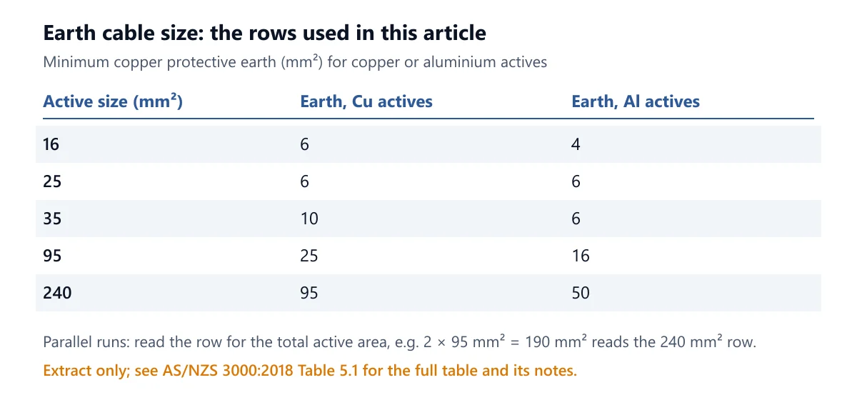
Read the row for the active conductor size. The table has a column for copper actives and one for aluminium actives; the earth itself is copper in both. The image below is an extract with only the rows this article uses; the full table and its notes are in the standard.
Three details trip people up:
Parallel runs are read by their total area. AS/NZS 3000:2018 Clause 5.3.3.1.2 takes parallel actives as the sum of their cross-sections. If the sum is not a tabulated size, read the next larger row. Two runs of 95 mm² copper total 190 mm², which reads the 240 mm² row: a 95 mm² copper earth, not the 25 mm² a single 95 mm² would need.
Aluminium actives need less copper earth than the same size of copper. 240 mm² aluminium actives need 50 mm² copper; 240 mm² copper actives need 95 mm². The table already accounts for the conductivity difference, so do not convert the aluminium size first. Our aluminium vs copper guide covers the rest of the trade-off.
Multicore cables come with their earth already sized. A 25 mm² four-core and earth typically carries an earth core matching Table 5.1 (6 mm²); confirm it on the manufacturer's data. If the checks below need more, you run a separate, larger earth alongside it.
Step 2: the adiabatic check for the fault current
AS/NZS 3000:2018 Clause 5.3.3.1.1 requires the earthing conductor to carry the prospective earth fault current for the operating time of the protective device. A fault lasts too briefly for the conductor to shed heat, so all the energy goes into heating it (the adiabatic assumption), and the minimum size is:
S = I√t / K
S: minimum earth conductor area, mm²
I: prospective earth fault current, A
t: clearing time of the protective device at that current, s
K: copper constant from AS/NZS 3008.1.1:2025 Table 5.1, set by the starting and final temperatures
The choice of K matters. An earth laid up in a cable with the actives, or run in the same enclosure, runs as hot as they do, so the calculator starts it at the insulation's maximum operating temperature. For V-75 PVC that gives K = 111.2 (75 °C to 160 °C); for X-90 XLPE, K = 142.9 (90 °C to 250 °C). The K of about 136 often quoted for copper earths corresponds to a PVC-insulated earth starting at 40 °C, one that is not run with the actives; using it for a TPS or four-core earth core understates the minimum by about 18%. The adiabatic equation itself is the subject of our article on fault current and cable sizing.
Worked example 1: when the fault current raises the earth
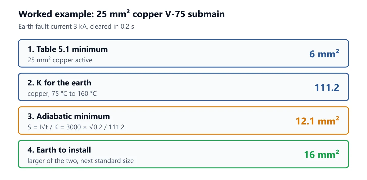
A 25 mm² copper V-75 four-core submain. The upstream device is a time-delayed breaker that clears a 3 kA earth fault in 0.2 s.
Table 5.1: 25 mm² copper active, so the minimum earth is 6 mm².
K: copper earth run with V-75 actives, 75 °C to 160 °C, K = 111.2.
Adiabatic minimum: S = 3000 × √0.2 / 111.2 = 1341.6 / 111.2 = 12.1 mm².
Earth to install: the larger of 6 and 12.1 mm², rounded up to a standard size: 16 mm².
The 6 mm² earth core in the cable would carry that fault for only (111.2 × 6 / 3000)² = 0.049 s before reaching 160 °C. With X-90 XLPE insulation instead, K rises to 142.9, the minimum falls to 9.4 mm², and a 10 mm² earth would do.
Worked example 2: when the table governs
A submain of two parallel runs of 95 mm² copper X-90 single-core cables, with a 20 kA prospective earth fault current cleared in 0.2 s (the example on the calculator page).
Total active area: 2 × 95 = 190 mm², which reads the 240 mm² row.
Table 5.1 earth: 95 mm².
Adiabatic minimum: 20,000 × √0.2 / 142.9 = 62.6 mm².
Result: 62.6 mm² is less than 95 mm², so the table governs. Install a 95 mm² copper earth.
The table can only be raised by the adiabatic check, never lowered. A small calculated minimum is not permission to install less than Table 5.1.
Step 3: the fault loop check
An earth that survives the fault can still be too long. The earth fault-loop impedance Zs must stay below Uo / Ia so the device trips instantaneously (see MCB trip curves for where Ia comes from). On long submains and final subcircuits this check, not the table, usually decides the earth cable size, because the earth is smaller than the active and contributes most of the resistance.
Take a 25 mm² copper V-75 four-core cable on a 400 V three-phase supply, 90 m long, protected by an 80 A type C MCB:
Uo = 400 / √3 = 230.9 V; Ia = 7.5 × 80 = 600 A; Zs max = 230.9 / 600 = 0.385 Ω.
With the 6 mm² Table 5.1 earth, Zs = 0.522 Ω: fail. Maximum length 66 m.
With a 10 mm² earth, Zs = 0.351 Ω: pass, maximum length 98 m.
With a 16 mm² earth, Zs = 0.258 Ω: pass, maximum length 134 m.
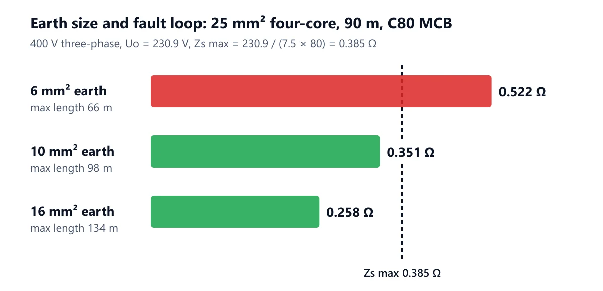
Upsizing the earth from 6 to 10 mm² fixes the loop without touching the actives. Upsizing the actives to 35 mm² would also raise the Table 5.1 earth to 10 mm², but costs far more copper for the same result. The theory of the loop is in our guide to fault loop impedance.
Common mistakes when sizing the earth
Reading Table 5.1 per run on parallel cables. Two 95 mm² runs need a 95 mm² earth (240 mm² row), not 25 mm². The table works on the total active area.
Using K = 136 for an earth core. That K assumes a cool earth not bundled with the actives. A TPS or four-core earth starts hot, so use the insulation's maximum operating temperature.
Checking only the maximum fault current. A lower earth fault current at the far end can mean a much longer clearing time on the thermal part of the curve, and therefore a larger I²t. With a real device curve, check the minimum earth fault current as well.
Using the clearing time of the wrong device. The time is that of the device protecting this circuit at this fault current, read from its curve, not the 0.4 s or 5 s disconnection limit.
Stopping at the table on long runs. The table says nothing about length. Every circuit needs the fault loop check, and the earth is often the cheapest place to fix it.
Forgetting equipotential bonding is a separate requirement. Main and supplementary bonding conductors have their own minimum sizes; this article covers protective earthing conductors for circuits.
FAQ
What size earth do I need for a 16 mm² cable?
For 16 mm² copper actives, Table 5.1 gives a 6 mm² copper earth; for 16 mm² aluminium actives, 4 mm². Then check the fault current and the fault loop, which may need more.
Can the earth be smaller than Table 5.1 if the fault current is low?
No. Table 5.1 is a minimum. The adiabatic and fault loop checks can only raise the earth size.
How do I size the earth for parallel cables?
Add the active areas of all runs, read the Table 5.1 row at or above the total, and install that earth. 2 × 95 mm² copper (190 mm²) reads the 240 mm² row: 95 mm².
Is the earth for aluminium cables copper or aluminium?
Table 5.1 gives a copper protective earth for both columns. The aluminium column is lower because aluminium actives carry less fault current per mm² than copper actives of the same size.
Size your earth in one place
In the Earth Cable Size Calculator, choose copper or aluminium, the insulation and the active size, enter the number of parallel runs, and add the prospective earth fault current and the device clearing time. It returns the Table 5.1 size, K, the adiabatic minimum and the earth to install, and says when the fault current raised it. Then put the same cable and earth into the Fault Loop Impedance Calculator with the route length and MCB to confirm the device trips in time. The Cable Short-Circuit Calculator runs the same adiabatic check for the actives. AS/NZS 3000:2018 is available from Standards Australia.
Work it out for your circuit
Free calculators, no sign-up needed.
Related articles
Continue reading more articles on this topic.
Standards & ComplianceSuheib
MCB Trip Curves Explained: Type B, C and D, Inrush and Maximum Zs
Type B, C and D MCBs share the same overload behaviour but trip instantaneously …
Read more: MCB Trip Curves Explained: Type B, C and D, Inrush and Maximum Zs
Product GuidesAhmed Tayeh
Effective Ways to Create AS/NZS-Compliant Single Line Diagrams
Single-line diagrams (SLDs) are simplified schematics that represent an electric…
Read more: Effective Ways to Create AS/NZS-Compliant Single Line Diagrams
Standards & ComplianceAhmed Tayeh
How to Integrate Fault Loop Impedance in Your Cable Sizing Calculations
Beyond matching conductor size to design current, correct cable sizing should al…
Read more: How to Integrate Fault Loop Impedance in Your Cable Sizing Calculations