

Updated 1 Nov 2026 · Reviewed by Ahmed Tayeh, electrical engineer
What the voltage rise calculator does
A grid-connected solar inverter pushes current back towards the network, so the voltage at its terminals sits above the voltage at the switchboard. If that voltage rise is too large, the inverter sees high voltage and trips or throttles its output on sunny days. The CableHero voltage rise calculator sizes the AC cable from the inverter so the voltage rise calculation for solar stays inside the 2% limit, and checks the same cable for current rating, short-circuit withstand and earthing.
It is the cable size calculator with its threshold switched to Rise: the same AS/NZS 3008.1.1:2025 engine, the same cards and the same report.
Before you start
- The inverter's rated AC output current (or rated power), and whether it is single phase or three phase.
- The cable route length from the inverter's AC terminals to the main switchboard, in metres.
- The cable type and how it is installed (in conduit, clipped, in a roof space, in insulation).
- The fault level at the switchboard, if you have it, for the short-circuit check.
- Your distributor's inverter connection rules, in case they set a tighter rise than 2%.
How to check solar voltage rise step by step
- 1
Enter the inverter output current
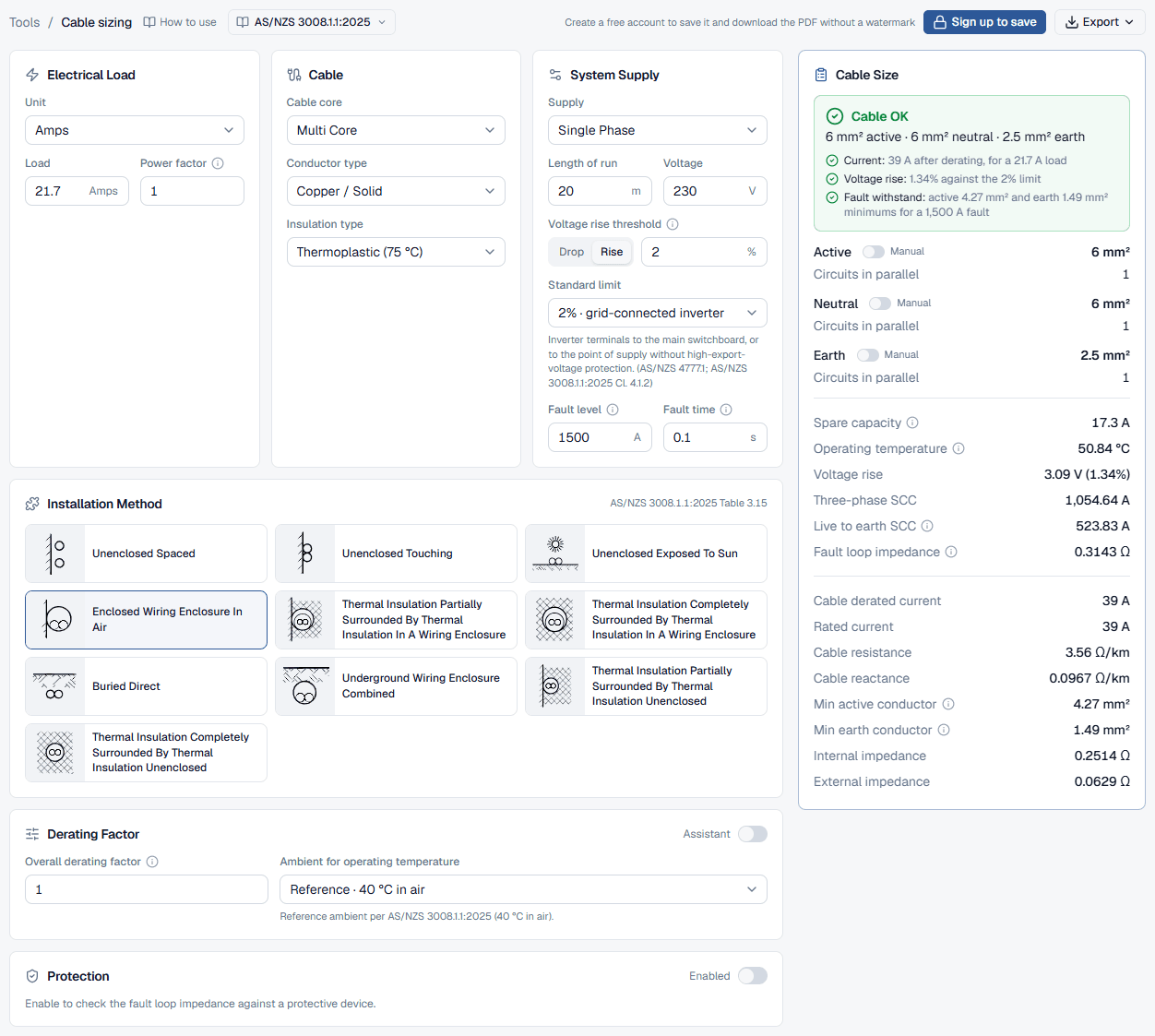
In Electrical Load keep the Unit on Amps and type the inverter's maximum continuous AC output current as the Load. You can enter kW instead; leave the Power factor at 1 for an inverter exporting at unity, so the current shown underneath matches the datasheet.
- 2
Switch the threshold to Rise
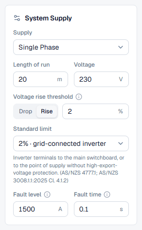
In System Supply choose the Supply, enter the Length of run and the Voltage, then click Rise beside the threshold. The field becomes Voltage rise threshold and the Standard limit switches to 2% · grid-connected inverter. Its hint says where the limit is measured: from the inverter terminals to the main switchboard, or to the point of supply without high-export-voltage protection. Type a smaller value if your distributor requires one.
- 3
Describe the cable and how it is installed
Fill in Cable, Installation Method and Derating Factor as for any circuit. Inverter cables often run through hot roof spaces or alongside other circuits, so set the ambient and grouping honestly: a hotter conductor has a higher resistance and a larger rise. Enter the Fault level and Fault time for the switchboard end.
The Distributed load switch is hidden in rise mode: the half-rating allowance is for load circuits only.
- 4
Read the voltage rise
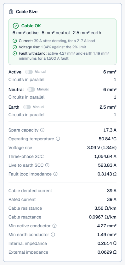
The Cable Size card picks the smallest cable within the rise threshold. The summary's Voltage rise line shows the percentage against the limit; the Voltage rise row gives volts and percent.
Reading the voltage rise result
A green Cable OK means the cable is within the rise threshold and passes the current, fault withstand and earthing checks. If you set the Active size by hand with the Manual switch (to check an existing cable, say), a rise above the threshold shows as a red Voltage rise line. The Operating temperature row explains small differences from a table lookup: a cable carrying well under its rating runs cooler and has a lower resistance.
Remember what the 2% covers. If the limit applies to the point of supply in your case, the consumer mains are part of the path, and the inverter cable gets only what is left after their rise at the inverter's output current.
Worked example: a 5 kW inverter 20 m from the switchboard
The public voltage rise calculator opens with this circuit: a single-phase inverter with a 21.7 A rated output (about 5 kW at 230 V), 20 m of two-core copper cable to the main switchboard, insulation Thermoplastic (75 °C), installation method Enclosed Wiring Enclosure In Air, fault level 1,500 A, and the 2% rise limit, which is 4.6 V at 230 V.
- 4 mm² is rated 30 A, plenty for 21.7 A, but rises 2.01% over the run, and fails on voltage rise and short-circuit withstand.
- 6 mm² is rated 39 A (17.3 A spare), runs at about 50.8 °C and rises 3.09 V (1.34%). It stays inside 2% for a run up to about 30 m.
Voltage rise best practice (AS/NZS 4777.1 2% limit)
- Check your distributor's rules: network service and installation rules and inverter connection agreements can set a lower figure, or measure it to a different point. Enter their figure as the threshold.
- Size for the inverter, not the array: the AC cable carries the inverter's output current. The d.c. string cables are sized separately; for those use DC with PV array circuit on, or the string voltage calculator for the string voltages.
- Allow for growth: if a battery or a larger inverter is likely, size the cable for the larger output now. Upsizing the cable is cheaper at installation than later.
- Mind the network voltage: sites with a high network voltage are the ones where inverters trip on overvoltage, so a cable that only just meets 2% leaves little margin. A size up costs little and keeps the inverter exporting.
Common voltage rise mistakes
Using the 5% voltage drop limit
5% is the load-side voltage drop limit in AS/NZS 3000:2018. An inverter circuit uses the 2% rise limit: select the Rise tab.Forgetting the consumer mains share
Where the limit is measured to the point of supply, the consumer mains carry the export too. Take their rise off the 2% before sizing the inverter cable.Entering a three-phase inverter as single phase
A three-phase inverter's output is shared across three phases at 400 V. Entered as single phase with the total current, the rise is grossly overstated.Using the panel or string current
The AC cable carries the inverter's rated AC output current, from the datasheet.