

Updated 1 Nov 2026 · Reviewed by Suheib Sherif, electrical engineer
What the fault loop impedance calculator does
When an active conductor touches earthed metalwork, the fault current flows out along the active, back along the protective earth and through the supply. That path is the earth fault loop, and its impedance, Zs, decides how much current flows. If Zs is too high the circuit breaker does not see enough current to trip instantaneously and the metalwork stays live. The free fault loop impedance calculator works out the circuit's Zs from the AS/NZS 3008.1.1:2025 conductor data and checks it against the maximum for a B, C or D curve MCB.
Use the fault loop impedance calculation:
- at design stage, to confirm a final subcircuit or submain can run the distance you need on the device you chose;
- to find the maximum route length for a cable and MCB combination before you quote a job;
- to test what changes (cable size, earth size, curve) bring a failing circuit back within the limit.
Before you start: inputs to collect
- Supply: single or three phase, and the nominal voltage (230 V or 400 V line voltage).
- Fault level at the origin in kA, from the switchboard schedule or the network operator. It only affects the earth fault current shown, not the Zs check.
- Protective device: the MCB curve and rating.
- Cable: multicore or single-core, copper or aluminium, insulation, active size, earth size if it is not the Table 5.1 minimum, any parallel runs, and the route length in metres (the cable length, not the straight-line distance).
How to calculate fault loop impedance, step by step
- 1
Set the supply
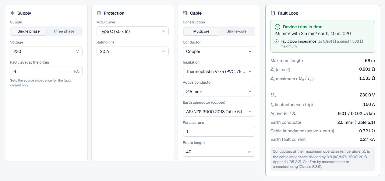
In the Supply card choose Single phase or Three phase. The voltage field follows the choice: Voltage (230 V) for single phase, Line voltage (400 V) for three phase, with a hint that Uo is the line voltage divided by √3. Enter the Fault level at the origin in kA.
- 2
Choose the protective device
In the Protection card pick the MCB curve. The options show the instantaneous trip multiple the calculator uses: Type B (4 × In), Type C (7.5 × In) and Type D (12.5 × In). Then choose the Rating (In), from 6 A to 125 A.
- 3
Describe the cable
In the Cable card set Construction (Multicore or Single-core), Conductor (copper or aluminium), Insulation and the Active conductor size. Leave Earth conductor (copper) on AS/NZS 3000:2018 Table 5.1 to use the minimum earth for the active size, or pick the size actually installed. Enter Parallel runs if the circuit uses more than one cable per phase, and the Route length in metres.
- 4
Read Zs against the maximum
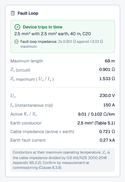
The Fault Loop card on the right recalculates as you type. The next section goes through each row.
Reading the Zs result
The headline reads Device trips in time when the check passes, or 1 check fails when it does not, with the circuit summarised underneath (for example the cable, earth, length and device). Below it:
- Maximum length: how far this cable can run on this device before Zs reaches the limit. It turns red when the route is longer.
- (circuit): the active plus earth impedance at maximum conductor temperature, divided by 0.8.
- maximum (): the limit for the device.
- and (instantaneous trip): the phase-to-earth voltage and the trip current the limit is built from.
- Active , Earth conductor and Cable impedance (active + earth): the cable data, so you can check the working.
- Earth fault current: the prospective current for a fault at the far end, using the fault level you entered.
Worked example: when a long run fails
Start with the calculator's default circuit: 230 V single phase, 6 kA at the origin, a C20 MCB and 2.5 mm² multicore V-75 copper cable with the Table 5.1 earth, 40 m long. It passes: Zs is 0.901 Ω against a maximum of 1.533 Ω, and the maximum length is 68 m.
Now change the Route length to 80 m. The headline turns to 1 check fails: Zs doubles to 1.802 Ω, above the 1.533 Ω limit, and the Maximum length row turns red at 68 m. Two changes in the calculator bring it back:
- Change the MCB curve to Type B. The trip current falls from 150 A to 80 A, so the limit rises to 2.875 Ω and the circuit passes with a maximum length of 127 m. Only do this if the load's inrush current will not trip a B curve.
- Increase the Active conductor to 4 mm². Rc drops from 9.01 Ω/km to 5.61 Ω/km and Zs to 1.462 Ω, a pass with 83 m available. The Table 5.1 earth stays 2.5 mm²; picking a larger earth in the Earth conductor field would lower Zs further.
Best practice and AS/NZS 3000 references
- Use Uo, per phase. The fault is phase to earth, so a three-phase circuit uses the line voltage divided by √3 (about 230.9 V at 400 V). The calculator does this when you choose Three phase.
- Leave room for the supply. The 0.8 factor allows for the impedance upstream of the circuit. On long submains or weak supplies, check the measured or declared external impedance too.
- Size the earth deliberately. The earth is often smaller than the active and carries the whole fault current back. When a run is long, check a larger earth before a larger active.
- Check fault loop alongside the other limits. The cable size calculator runs this check with current rating, voltage drop and short-circuit withstand, and steps the cable up until all pass.
Common fault loop mistakes
Entering 400 V as Uo
Choose Three phase and enter the line voltage. The fault is between one phase and earth, so the calculator works with 400 V / √3.Ignoring the upstream 20%
Comparing the cable impedance alone with Uo / Ia overstates the allowed length. The calculator divides by 0.8 for you; keep that margin when you check by hand.Assuming the earth is the same size as the active
Twin and earth cables and many multicores have a smaller earth. Leave the field on Table 5.1, or pick the size that is actually installed.Using the straight-line distance
Enter the cable route length, including risers, drops and detours, not the distance on the floor plan.Changing to a B curve without checking the load
A B curve passes more easily but trips on high inrush loads such as motors and transformers. Upsizing the cable may be the better fix.