
Updated 1 Nov 2026 · Reviewed by Suheib Sherif, electrical engineer
What the cable short-circuit calculator does
During a short circuit the current through a cable can be hundreds of times its rating. The protective device clears it in a fraction of a second, but until it does, the conductor heats up fast enough to damage the insulation. The free cable short-circuit calculator checks whether a conductor survives that heat, using the adiabatic equation of AS/NZS 3008.1.1:2025:
The energy the fault lets through () must not exceed what the conductor can absorb before the insulation reaches its limit (). The calculator gives the pass or fail, the minimum conductor size and how long the cable can carry the fault.
Use the cable short-circuit calculation when you:
- connect a small cable close to a large transformer or main switchboard, where fault levels are high;
- reuse an existing cable on a new, stronger supply;
- choose between V-75 and X-90 insulation, or between two protective devices with different clearing times.
Before you start: fault current and clearing time
- Prospective short-circuit current at the origin of the circuit, in kA: from the switchboard's fault level, the network operator, or an upstream fault calculation.
- Clearing time in seconds: from the protective device's time-current curve at that current.
- The conductor: copper or aluminium, insulation type and size in mm².
How to check cable short-circuit withstand, step by step
- 1
Describe the conductor
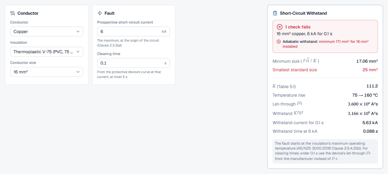
In the Conductor card choose the Conductor material (Copper or Aluminium) and the Insulation: Thermoplastic V-75 (PVC, 75 °C), XLPE or elastomer X-90 (90 °C) or Fire rated (110 °C). The insulation sets both the starting temperature and the limit temperature, and so K. Then pick the Conductor size, 1 mm² to 630 mm².
- 2
Enter the fault
In the Fault card enter the Prospective short-circuit current in kA. The hint reminds you to use the maximum, at the origin of the circuit. Enter the Clearing time in seconds, read from the device's curve; the field accepts 0.01 s to 5 s.
- 3
Read the withstand check
The Short-Circuit Withstand card updates as you type. The next section explains each row.
Reading the short-circuit withstand result
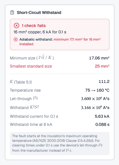
The headline reads Conductor withstands the fault when it passes, or 1 check fails when it does not, with the size, material, current and time underneath. The rows are:
- Minimum size (): the smallest cross-section that survives, to two decimals.
- Smallest standard size: the next size on the ladder at or above the minimum. It turns red, saying the chosen size is too small, when the check fails.
- (Table 5.1) and Temperature rise: the constant and the start and limit temperatures it is read for.
- Let-through and Withstand : the two sides of the equation in A²s.
- Withstand current for the entered time, and Withstand time at the entered current: how much headroom the cable has, either way.
Worked example: a 16 mm² cable at 6 kA
A 16 mm² copper cable with Thermoplastic V-75 (PVC, 75 °C) insulation is fed from a board with a prospective fault of 6 kA, and the upstream device clears it in 0.1 s. With those values entered the card shows 1 check fails:
The 16 mm² V-75 conductor needs at least 17.06 mm², so the smallest standard size is 25 mm². It can only carry 6 kA for 0.088 s, less than the 0.1 s the device takes. Two changes in the calculator fix it:
- Set Conductor size to 25 mm². The withstand rises to 7.73 × 10⁶ A²s and the cable lasts 0.215 s at the fault current.
- Keep 16 mm² and change Insulation to X-90. K rises to 142.9 because the limit temperature is higher, the minimum falls to 13.28 mm², and the cable passes with 0.145 s of withstand.
A faster device is the third option: enter its clearing time and see whether the original size passes.
Best practice and the adiabatic equation in AS/NZS 3008
- Take the clearing time from the device. Read it from the time-current curve at the prospective fault current, not from a disconnection-time table.
- Use let-through energy for very fast devices. Below about 0.1 s, compare the manufacturer's let-through I²t with the Withstand K²S² row instead of entering a time.
- Check at the start of the cable. The fault at the origin is the largest; the far end has the most impedance and the lowest current.
- Run it inside the cable sizing. The cable size calculator does this check for the active and the earth together with current rating, voltage drop and fault loop.
Common short-circuit mistakes
Entering 0.4 s or 5 s by default
Those are disconnection-time limits. The device usually clears a large fault much faster, or much slower near its overload region. Use the curve.Using the fault current at the far end
The adiabatic check uses the maximum prospective current at the origin of the circuit.Starting the fault cold
A conductor at ambient temperature has a higher K. The calculator starts at the insulation's maximum operating temperature; do the same in a hand check.Picking the minimum size instead of a standard size
The Minimum size row is a calculated cross-section. Install at least the Smallest standard size shown below it.